
By the Engineering Team at Butler Technologies, Inc.
For engineers designing the next generation of medical devices or industrial controls, the user interface (UI) is the critical bridge between human intent and machine action. While touchscreens are ubiquitous in consumer electronics, mission-critical applications often rely on a more rugged, tactile, and reliable solution: the membrane switch.
But what exactly is happening beneath that flexible surface?
To the end user, it is a simple button. To an engineer, it is a complex assembly of polymer films, conductive inks, and precise adhesives. Here is a technical deep dive into the anatomy of a membrane switch, how it functions, and why leading manufacturers utilise specific materials for longevity.
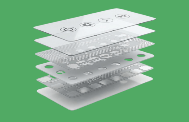
The Anatomy: Deconstructing the "Sandwich"
A membrane switch is essentially a momentary electrical contact switch made of flexible layers. Unlike mechanical switches that rely on bulky copper and plastic parts, membrane switches are printed.
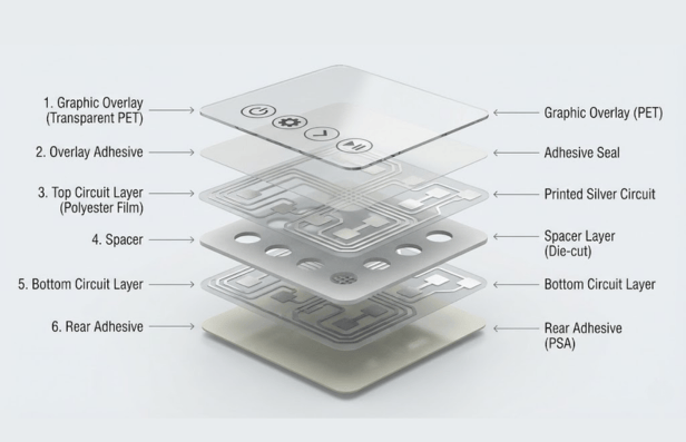
While custom stack-ups vary based on the application (e.g., shielding requirements), a standard high-reliability switch consists of six critical layers.
1. The Graphic Overlay (The Face)
This is the top layer—the interface the user sees and touches.
- Material: Typically chemically resistant polyester (PET) or Polycarbonate.
- Function: It provides the visual guide (branding, icons, text) and hermetically seals the switch from the environment.
- Engineering Note: At Butler Technologies, we often utilise "selective texturing" on this layer—keeping window areas glossy for LCD readability while texturing buttons for durability and grip.
2. The Overlay Adhesive
This layer bonds the graphic overlay to the top circuit. It is die-cut to match the shape of the switch, ensuring a watertight seal. This perimeter seal is what allows membrane switches to achieve IP65 and IP67 ratings, making them impervious to dust and moisture.
3. The Top Circuit Layer (The Mover)
In a standard flexible design, this layer is a thin polyester film printed with conductive silver ink.
- Tactile vs. Non-Tactile: If the switch uses metal domes for feedback, this layer acts as the "dome retainer." When you press the button, this layer flexes or the dome collapses.
4. The Spacer (The Insulator)
This is the "air gap." It is an adhesive layer with precision cutouts at the switch locations. Its primary job is to keep the top and bottom circuits separated (open) until a user intentionally presses a button. The thickness of this spacer determines the actuation force and travel distance.
5. The Bottom Circuit Layer (The Base)
This static layer contains the mating conductive pads and the circuitry that routes the signal to the "tail" (the flexible ribbon cable that plugs into your device's PCB).
- Advanced Capabilities: This layer is where modern innovation happens. Manufacturers like Butler Technologies can integrate Printed Electronics—such as Force Sensing Resistors (FSR), biometric sensors, or printed heaters—directly into this layer, reducing component count and assembly time.
6. The Rear Adhesive
The final layer is a pressure-sensitive adhesive (PSA) that bonds the entire switch assembly to the product's rigid housing or backer panel.
How It Works: The Mechanics of Actuation
A common query for product designers is the specific mechanism of action. Put simply, a membrane switch is a Normally Open (NO) momentary contact.
- Rest State: The spacer layer holds the top and bottom conductive layers apart. No current flows.
- Actuation: The user applies force (typically 200g–500g) to the graphic overlay.
- Contact: The top layer flexes through the spacer cutout. The conductive ink (or metal dome) touches the bottom circuit traces.
- Signal: The circuit closes, sending a low-voltage signal through the tail to the device controller.
- Release: When pressure is removed, the elasticity of the film (or the snap of the dome) returns the switch to its open state.
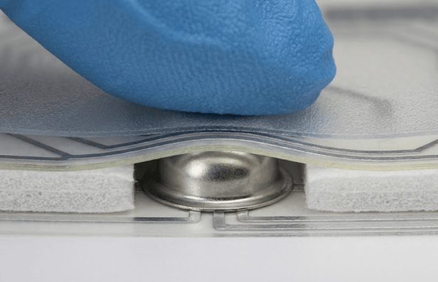
The "Click" Factor: Tactile vs. Non-Tactile
- Tactile Switches: These provide a physical "snap" or "click" upon actuation, usually achieved by placing a stainless steel dome inside the layer stack. This is preferred in medical devices where "blind" operation is necessary.
- Non-Tactile Switches: These are silent and rely on visual (LED) or audio (beep) feedback from the device. They are ideal for flat, easy-to-clean panels in sterile environments.

Engineering for Reality: Durability and Environment
A membrane switch is only as good as its materials. When sourcing a manufacturer, it is vital to ask about material selection for harsh environments.
Silver Flex vs. Copper Flex
- Silver Flex: The industry standard. Conductive silver ink is screen-printed onto polyester. It is cost-effective and reliable for most interfaces.
- Copper Flex: For designs requiring miniaturisation or soldered components (like LEDs and resistors) directly on the tail, Copper Flex (etched copper on polyimide) is the superior choice. This technology allows for denser circuit routing and higher conductivity.
Lifespan Expectations
A well-engineered switch is built to last.
- Non-tactile switches can exceed 5 million actuations.
- Metal dome switches are typically rated for 1 million+ actuations.
The Butler Technologies Difference
We are not just a print shop; we are a solutions provider. From the proof-of-concept phase to full-scale production, our team integrates design, engineering, and manufacturing under one roof in the USA.
- ISO Certified Quality: With ISO 9001:2015 certifications, we ensure every layer meets strict regulatory standards.
- Printed Electronics Pioneers: We push the boundaries of what a "switch" can do, integrating heaters, sensors, and antennas directly into the flexible interface.
Ready to start your design? Whether you need a simple keypad or a complex biometric interface, successful products start with the right engineering partner.
Contact the Butler Technologies Engineering Team to discuss your project requirements or request a material sample kit.