

Download full Datasheet here: Product Datasheet
Overview
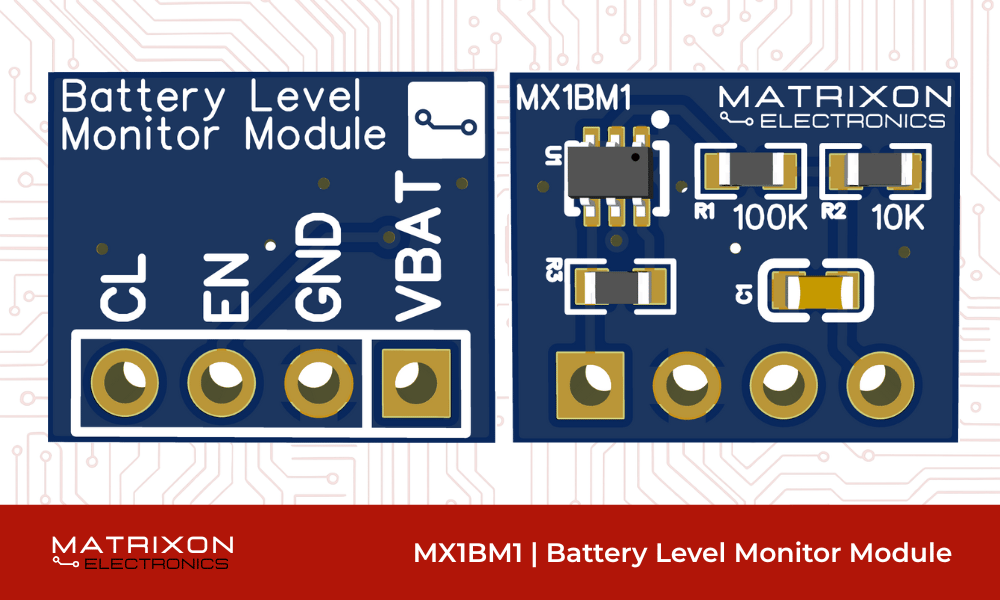
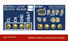
The MX1BM1 - Battery Level Monitor Module is a compact, low-power board designed to measure battery voltage. It safely scales battery voltages (3.0V to 5.2V) for ADC input on MCUs like ESP32, STM32, Arduino, etc. It features an enable-controlled voltage divider with MOSFET gating for low standby current, ideal for deep-sleep applications.
Key Features
- Input voltage: 3.0V to 5.2V (VBAT)
- Output: Scaled analog voltage for 3.3V ADCs
- Enable-controlled voltage divider (low-power)
- 10µF smoothing capacitor for clean ADC readings
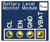
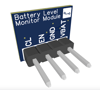
- Standard 2.54mm 4-pin header for easy integration
- Breadboard-friendly and compact
Applications
- Battery-powered IoT devices
- Remote sensor nodes
- Device battery level reporting
- Low-voltage cut-off / battery protection systems
- USB power diagnostics
- Smart wearables and embedded systems
Purchase Link
Download the Gerber files here: MX1BM1 - Battery Level Monitor Module
Example Arduino sketch: Example Code.ino
Enable Logic
- Logic HIGH (≥2.5V): Enables the voltage divider and outputs the scaled voltage
- Logic LOW (0V): Turns off the divider to reduce standby current
- Compatible with 3.3V microcontrollers (ESP32, STM32, etc.)
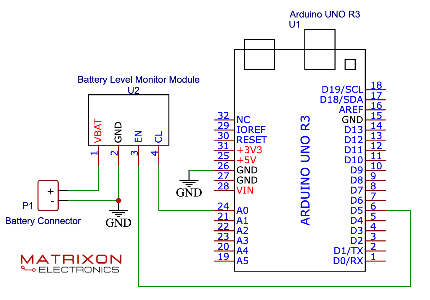
Example Application
Example Arduino Code
#define EN_PIN 5
#define CL_PIN A0
void setup() {
pinMode(EN_PIN, OUTPUT);
digitalWrite(EN_PIN, LOW);
Serial.begin(9600);}
void loop() {
digitalWrite(EN_PIN, HIGH); // Enable module
delay(5); // Wait for stable output
int raw = analogRead(CL_PIN); // Read ADC value
digitalWrite(EN_PIN, LOW); // Disable module
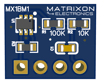
// Voltage divider: R1 = 100k, R2 = 10k
// Divider ratio: CL = VBAT * (10 / 110) = VBAT * 0.0909
// So, VBAT = CL / 0.0909
float v_adc = raw * (3.3 / 4095.0); // ADC (assuming 12-bit ADC and 3.3V ref)
float battery_voltage = v_adc / 0.0909; // Reconstruct battery voltage
Serial.print("Battery Voltage: ");
Serial.print(battery_voltage, 2); // 2 decimal places
Serial.println(" V");
delay(1000);}
This code enables the Battery Level Monitor Module by setting the EN pin HIGH, allowing the voltage divider to output the scaled battery voltage to the CL pin. The microcontroller then reads this voltage using its ADC and calculates the actual battery voltage using the known divider ratio (R1 = 100k, R2 = 10k). After reading, the module is disabled to save power. The measured battery voltage is printed to the Serial Monitor once every second.
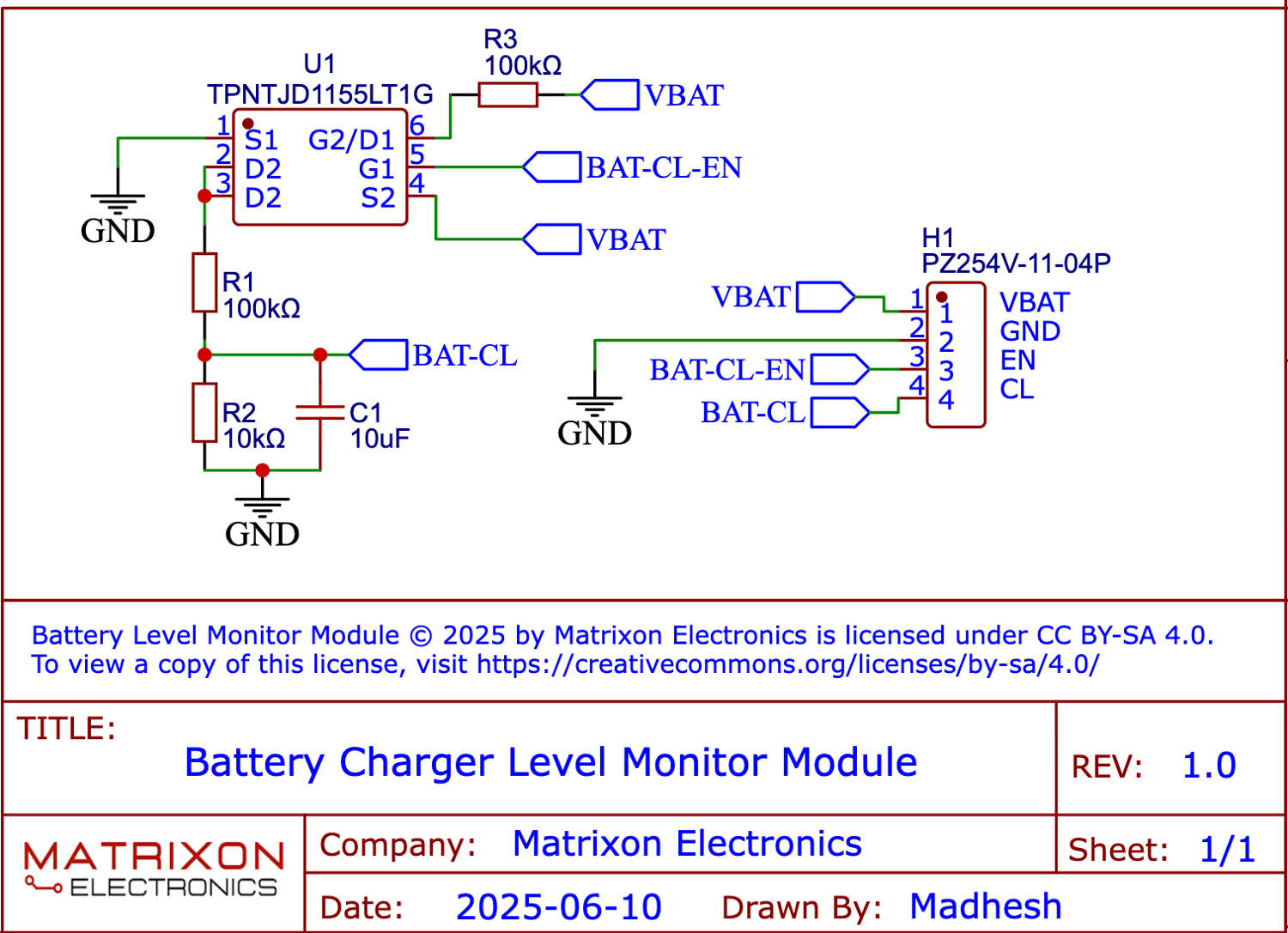
Schematic Diagram