
Toyota 7BRU18 7BRU23 7BDRU15 7BSU20 7BSU25 Reach Lift Truck Workshop Repair Service Manual PDF - MTOINCL220.zip
Full service and repair documentation, complete with Electrical Wiring Diagrams, covering Toyota Reach Lift Truck Models 7BRU18, 7BRU23, 7BDRU15, 7BSU20, 7BSU25 — everything needed to service, troubleshoot, fix, and overhaul these trucks the way expert technicians do.
Included in the workshop service repair manual for Toyota Reach Lift Truck Models 7BRU18, 7BRU23, 7BDRU15, 7BSU20, 7BSU25:
* Numbered table of contents easy to use so that you can find the information you need fast.
* Detailed sub-steps expand on repair procedure information
* Numbered instructions guide you through every repair procedure step by step.
* Troubleshooting and electrical service procedures are combined with detailed wiring diagrams for ease of use.
* Notes, cautions and warnings throughout each chapter pinpoint critical information.
* Bold figure number help you quickly match illustrations with instructions.
* Detailed illustrations, drawings and photos guide you through every procedure.
* Enlarged inset helps you identify and examine parts in detail.
PRODUCT DETAILS:
Total Pages: 557 pages
File Format: PDF (Internal Links, Bookmarked, Table of Contents, Searchable, Printable, high quality)
Language: English
00700-CL220-01 - Toyota Reach Lift Truck Model 7BRU18, 7BRU23, 7BDRU15, 7BSU20, 7BSU25 Service Manual.pdf
MAIN SECTIONS
R/M 7BRU18-23, 7BDRU15 & 7BSU25 SN: 21,000 & UP - 24 VOLT MODELS & SN: 32,000 & UP - 36 VOLT...1
Table of Contents...I
How to Use This Manual...1
Map of the Manual...2
Manual Design...3
START Page...5
Safety...1
Definitions...2
General Safety...3
Battery Safety...7
Static Safety...11
Figure 2-1: Ground Jack...11
Figure 2-2: Anti-Static Kit with Wrist Strap and Mat...12
Jacking Safety...13
Figure 2-3: Correct Jacking Locations...13
Tie-down for Transport...14
Welding Safety...15
Systems Overview...1
Vehicle Specifications...2
General System Data...3
Brake...4
Steering...4
Lift/Lower System...4
Auxiliary System...4
Traction System...5
Modes of Operation...6
Self-diagnosis Mode...6
Analyzer (AnL) Mode...6
Tuning (Tuning) Mode...6
Calibrate (Calibrte) Mode...6
Configure (Configur) Mode...6
Scheduled Maintenance...1
Maintenance Guidelines...2
Daily or Every 8 Operating Hours...3
Monthly or Every 200 Operating Hours...4
Semi-annually or Every 1000 Operating Hours...5
Annually or Every 2000 Operating Hours...6
Lubricants...7
Cold Storage Conditioning...7
Classes Of Cold Storage...7
Figure 4-1: Recommended Oils by Temperature...7
Lubrication and Inspection Points...9
Figure 4-2: Lubrication and Inspection Points...9
Troubleshooting...1
How to Use This Chapter...2
Electrical Troubleshooting Guidelines...3
Shorts to Frame Test...4
To test for shorts to frame:...4
Figure 5-1: Shorts to Frame Test...6
Hydraulic Troubleshooting Guidelines...8
Definitions...9
Auxiliary Function...9
Continuity...9
Deadman Switch...9
High Speed Travel Limit...9
Mast Assembly...9
Mast Switch...9
Open Circuit...9
Overtemperature (Power Amplifiers)...9
Pulse Width Modulation...9
Short Circuit or “Short”...9
Tractor...9
Undertemperature...9
Electrical Connector Locator Chart...10
Electrical Connector Locator Photos...12
Figure 5-2: Electrical Connectors, Electrical Compartment (Operator Right Side)...12
Figure 5-3: Power Amplifier Connections...13
Figure 5-4: Electrical Connectors, Motor Compartment...14
Figure 5-5: Electrical Connectors, Operator Display/Display Card...15
List of Troubleshooting Flowcharts...17
Hydraulic Charts...17
Travel Charts...17
Wiring Charts...17
TS1: START TROUBLESHOOTING...19
GEN1: General Troubleshooting...20
MISC: Miscellaneous Problems...21
END1: End of Troubleshooting Procedure...22
H-1: Hydraulic Problem with One Function...23
H-2: Lift/Lower Problem...24
H-3: Reach Problem...25
H-4: Retract Problem...26
H-5: Tilt Problem...27
H-6: Sideshift Problem...28
H-7: Hydraulic Problem...29
H-10: Lift Does Not Respond for Lift or Aux. Function...30
H-11: No Lift, Lift Motor Operates...33
H-12: Lift Functions But Works Slow, Lift Motor Runs...38
H-13: Reach Does Not Work...42
H-14: Reach Works Slow...46
H-15: Reach and Lift Pump Do Not Work...49
H-16: Retract Does Not Work...50
H-17: Retract Works Slow...54
H-18: Retract and Lift Pump Do Not Work...57
H-19: Tilt Does Not Work (Up or Down)...58
H-20: Tilt Works Slow...61
H-21: Tilt and Lift Pump Do Not Work...63
H-22: Sideshift Does Not Work (Either Direction)...64
H-23: Sideshift Works Slow...67
H-24: Sideshift and Lift Pump Do Not Work...69
H-25: Load Drifts Down While Forks Are Elevated...70
H-26: Cannot Pick Up A Load...72
H-27: Aux Functions Work Only One Side/Direction...74
H-28: No Lower...76
T-1: Travel Problem...80
T-2: No Travel In Either Direction...81
T-3: Travel In One Direction Only...83
T-4: Problem With Slow Travel...84
T-5: Truck Does Not Accelerate Properly...85
T-6: Plugging Does Not Operate Properly...87
T-18: No Slow Travel Above Mast Switch1...88
T-19: Slow Travel Speed At All Times...89
W-1: Truck Functions Partially...92
Electrical Codes and Tests...1
Modes of Operation...2
Figure 6-1: Menu Structure for Modes of Operation...2
Passwords...3
Disable the Brush Wear Warning...3
Start the Hour Meter...3
Self-diagnosis Mode...4
Maneuvering within Self-diagnosis Mode...4
Adjusting the Date...4
Adjusting the Time...4
Analyzer (AnL) Mode...5
Entering the Secondary Password...5
Entering Analyzer Mode...5
Maneuvering within Analyzer Mode...5
Calibrate (Calibrte) Mode...6
Entering the Secondary Password...6
Entering Calibrate Mode...6
Maneuvering within Calibrate Mode...6
Configure (Configur) Mode...8
Entering the Secondary Password...8
Entering Configure Mode...8
Maneuvering within Configure Mode...8
Exiting Configure Mode...8
Tuning (Tuning) Mode...9
Entering the Secondary Password...9
Maneuvering within Tuning Mode...9
Exiting Tuning Mode...11
Code Summary Table...12
Table 6-1: Steer Controller Codes...82
Table 6-2: Steering Counterclockwise...93
Table 6-3: Steering Clockwise...93
Tests...122
Test 11 - Simple Test...123
Test 12 - Analog Inputs...124
Test 13 - Traction Speed Sensor...127
Test 14 - Throttle/Lift Command Test...128
Test 21 - Error Code Display...129
Test 33 - Switch Input Test...130
Test 34 - Short Circuit Test...131
Test 41 - Drive Unit Proximity Sensor Test (180 Steering)...132
Test 41 - Drive Unit Proximity Sensor Test (360 Steering)...133
Test 51 - Output Test...134
Test 61 - Software Versions...135
Analog Tests (Category 1, Class 2)...136
Test 12-00 - Drive Motor Armature Current...136
Test 12-01 - Drive Motor Field Current...136
Test 12-02 - Traction Pot. Voltage...137
Test 12-03 - Traction Motor Temperature Sensor...137
Test 12-04 - Traction Motor Power Amplifier Temperature Sensor...138
Test 12-05 - Lift Motor Armature Current...138
Test 12-06 - Lift Pot Voltage...138
Test 12-07 - Lift Motor Temperature Sensor...139
Test 12-08 - Lift Motor Power Amplifier Temperature Sensor...139
Test 12-10 - Pressure Transducer...140
Test 12-11 - Battery Voltage...140
Test 12-12 - Stored Battery Voltage...140
Test 12-13 - 12V Supply on the Display Card...141
Test 12-14 - MM Contactor Sense...141
Test 12-15 - EPO Sense...141
Test 12-16 - Left Pedal Pot...142
Component Procedures...1
List of Component Procedures...2
Component Locator Photos...5
Frame and Accessories...13
Panels and Covers...14
General...14
Figure 7-1: Tractor Panels and Covers...14
Console Cover...14
Electrical Compartment Access Panel...15
Motor Compartment Door...15
Left Operator Compartment Panel...16
Left Side Panel...16
Floor Board...18
Figure 7-2: Floor Board Removal...18
Decals...20
Decal with Protective Sheet...20
Decal without Protective Sheet...20
Steering and Controls...21
Steering Wheel...22
Figure 7-3: Steering Wheel Mounting and Components...22
Removal...22
Installation...22
Steer Tachometer...23
Figure 7-4: Steer Tach Mounting...23
Steer Motor...24
Figure 7-5: Steer Motor...24
Figure 7-6: Spacer and O-Rings...24
Figure 7-7: Mounting Bolts and Grommets...25
Steer Motor Gear Replacement...25
Figure 7-8: Steer Motor Gear...25
Steer Controller...26
Figure 7-9: Steer Controller...26
Exterior Cleaning...26
Removal...26
Installation...27
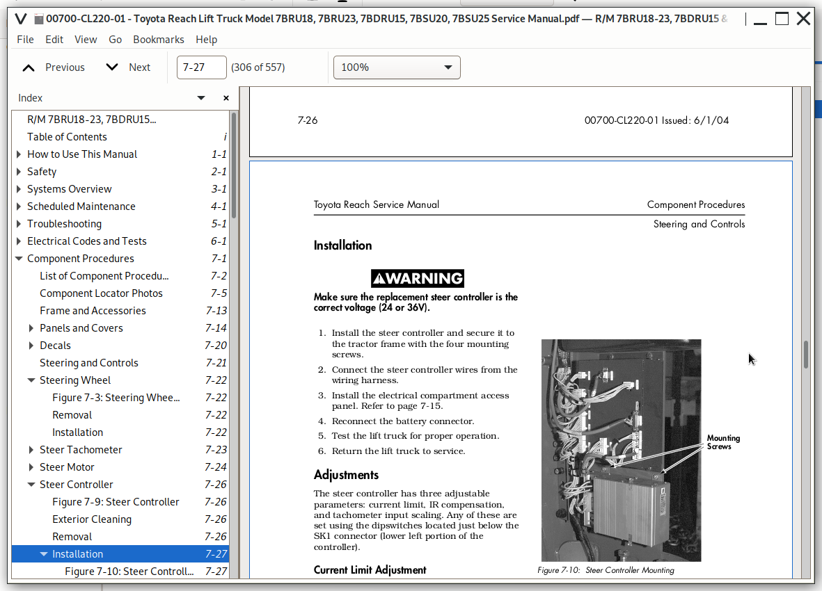
Figure 7-10: Steer Controller Mounting...27
Adjustments...27
Control Handle...29
Figure 7-11: Control Handle...29
Figure 7-12: Control Handle Mounting Screw...29
Figure 7-13: JP10 Connection at Tractor Interface Card...29
Traction and Braking...31
Deadman Pedal...32
Figure 7-14: Deadman Pedal Component Identification...32
Pedal Bearing Replacement...34
Caster Assembly with Brake...35
Figure 7-15: Caster Assembly with Brake Component Identification...35
Caster Brake Adjustment...36
Figure 7-16: Upper Adjustment Location...37
Figure 7-17: Lower Adjustment Location...38
Caster Assembly w/o Brake...41
Figure 7-18: Caster Assembly without Brake Component Identification...41
Caster Pivot...42
Thrust Bearing...44
Figure 7-19: Jacking Location...44
Caster Springs...45
Figure 7-20: Caster Adjustment Springs...45
Caster Axle...47
Caster Stops...48
Electromagnetic Brake...51
Figure 7-21: Brake Components...51
Coil Check On Brake...53
Electromagnetic Brake, Armature and Magnetic Coil...54
Removal...54
Installation...54
Brake Friction Plate...55
Inspection...55
Figure 7-22: Friction Plate...55
Replacement...55
Drive Wheel...56
Figure 7-23: Drive Wheel Components...56
Removal...56
Figure 7-24: Jacking Tractor End...56
Figure 7-25: Drive Wheel and Tire...57
Installation...57
Figure 7-26: Drive Tire Installation...58
Drive Tire Pressing Procedure...58
Drive Unit...60
Figure 7-27: Drive Unit Drain Plug...60
Fluid Changing Procedure...60
Removal...60
Figure 7-28: Drive Tire Cradle for Drive Unit...61
Installation...61
Tooth Pattern of Drive Unit...62
Figure 7-29: Drive Unit Gear Tooth Pattern...62
Drive Housing Steering Bearing...63
Figure 7-30: Steering Bearing Location...63
Removal...63
Installation...64
Axle Seal Replacement...65
Figure 7-31: Lower End of Drive Unit...65
Procedure...65
Figure 7-32: Ring Gear Before Being Pressed Toward Flange...65
Figure 7-33: Ring Gear After Being Pressed Toward Flange...65
Figure 7-34: Removing Bearing Spacer Using Bearing Puller...66
Figure 7-35: Removing External Snap Ring...66
Figure 7-36: Removing Output Shaft...66
Figure 7-37: Removal/Installation of Shaft Seal...67
Figure 7-38: Installing Ring Gear...67
Electrical...69
Battery...70
Figure 7-39: Battery Connector...70
Removal...70
Installation...70
Figure 7-40: Battery Gate...71
Battery Gates...71
Figure 7-41: Battery Rollers...71
Battery Rollers...71
Battery Maintenance...72
Battery Inspection and Care...72
Battery Exterior Cleaning...72
Charging...73