
Mercedes-Benz E-Class C238 A238 Coupe Cabriolet Workshop Service Repair Manual 2016-2023 PDF - MMBW238E.zip
This complete factory-level service and repair manual for the Mercedes-Benz E-Class Coupe & Cabriolet (C238 / A238) comes with full Electrical Wiring Diagrams, giving you every piece of technical data needed to service, troubleshoot, fix, and rebuild your vehicle the way professional technicians do.
Inside the Mercedes-Benz E-Class Coupe_Cabriolet (C238_A238) workshop service repair manual, you'll find:
* Numbered table of contents easy to use so that you can find the information you need fast.
* Detailed sub-steps expand on repair procedure information
* Numbered instructions guide you through every repair procedure step by step.
* Troubleshooting and electrical service procedures are combined with detailed wiring diagrams for ease of use.
* Notes, cautions and warnings throughout each chapter pinpoint critical information.
* Bold figure number help you quickly match illustrations with instructions.
* Detailed illustrations, drawings and photos guide you through every procedure.
* Enlarged inset helps you identify and examine parts in detail.
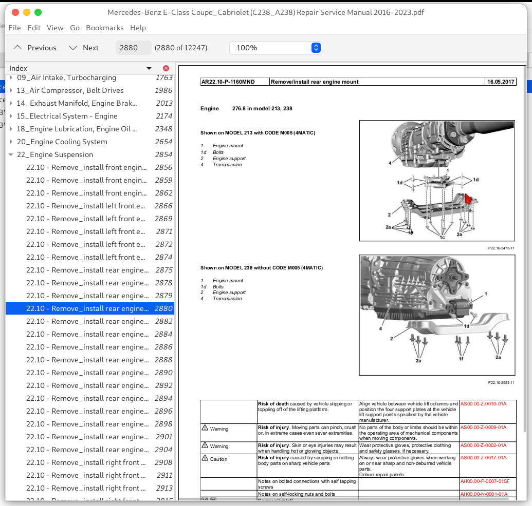
Mercedes-Benz E-Class Coupe_Cabriolet (C238_A238) Repair Service Manual 2016-2023.pdf
PRODUCT DETAILS:
Total Pages: 12,112 pages
File Format: PDF (Internal Links, Bookmarked, Table of Contents, Searchable, Printable, high quality)
Language: English
3dr Coupe (2.0 diesel [E220d] / 3.0 diesel [E350d/E400d] / 2.0 petrol [E300] / 3.0 petrol [E400/E 53 AMG])
2dr Cabriolet (2.0 diesel [E220d] / 3.0 diesel [E350d/E400d] / 2.0 petrol [E300] / 3.0 petrol [E400/E 53 AMG])
TABLE OF CONTENTS
00_Overall Vehicle...3
00.00 - 00 - Acronyms Used in the Diagnostic Manual Passenger Cars (dh0000p0ac00ux)...21
00.00 - 00 - Connection and Use of Test Equipment 1 - Explanation of Symbols Used for Test Equipment and Components Passenger cars (dh0000p0a001ux)...23
00.00 - 00 - Connection and Use of Test Equipment 2 - Connector Layout of Data Link Connector Passenger cars (dh0000p0a002ux)...24
00.00 - 00 - Connection and Use of Test Equipment 3 - Connecting HHT or Impulse Counter Scan Tool, Reading and Erasing Diagnostic Trouble Code Memory - Passenger cars (dh0000p0a003ux)...26
00.00 - 00 - How to Use the Diagnostic Manual Passenger Cars (dh0000p0aan0ux)...29
00.00 - 00 - How to use the Diagnostic Manual Passenger Cars (dh0000p0can0ux)...31
00.00 - 00 - Preface - Diagnostic Manual Passenger cars (dh0000p0avt0ux)...33
00.00 - 00 - Survey of Tests Chassis and Drivetrain Volumes 1 thru 3 Passenger Cars (dh0000pf0up0ux)...34
00.00 - 00 - Survey of Tests Diagnosis - Gasoline engine Engines 102, 103, 104, 111, 112, 113, 116, 117, 119, 120 (dh0000pm0up0ux)...35
00.00 - 00 - Survey of Tests Diagnostic Manuals Body and Accessories Passenger Cars (dh0000pa0up0ux)...36
00.00 - 00 - Survey of Tests Information and Communication Volume 1 Passenger Cars (dh0000pi0up0ux)...38
00.00 - 00 - Survey of Tests Passenger Cars (dh0000p10up0ux)...39
00.00 - 00 - Survey of Tests Passenger Cars Typen 129, 140, 163, 170, 202, 208, 210 (dh0000pk0up0ux)...40
...
07.02 - Remove_install high-pressure fuel pump (ar07.02-p-1028mnd)...1198
07.02 - Remove_install high-pressure fuel pump (ar07.02-p-1028mrh)...1202
07.02 - Remove_install housing of high-pressure fuel pump (ar07.02-p-1026mnd)...1206
07.02 - Tightening procedure for housing of fuel system high pressure pump (ar07.02-p-1020-02mm)...1208
07.03 - Check fuel high pressure circuit. (ar07.03-p-1010-04mm)...1210
07.03 - Check high-pressure lines (ar07.03-p-1010-03mm)...1211
07.03 - Mount high-pressure lines. (ar07.03-p-1010-02mma)...1212
07.03 - Reduce fuel pressure through service valve (ar07.03-p-1460-01va)...1214
07.03 - Relieve fuel pressure (ar07.03-p-1460-02mm)...1216
07.03 - Remove injection nozzles (ar07.03-p-0004-03mm)...1217
07.03 - Remove_install fuel injectors of left cylinder bank (ar07.03-p-0013mnd)...1218
07.03 - Remove_install fuel injectors of right cylinder bank (ar07.03-p-0014mnd)...1219
07.03 - Remove_install fuel injectors sealing package on rail (ar07.03-p-0004-02mm)...1220
07.03 - Remove_install left rail (ar07.03-p-1011mnd)...1223
07.03 - Remove_install low-pressure line (ar07.03-p-1120mrh)...1227
07.03 - Remove_install rail with fuel injectors (ar07.03-p-1052mrh)...1230
07.03 - Remove_install right rail (ar07.03-p-1012mnd)...1236
07.03 - Replace fuel injector sealing ring (ar07.03-p-0004-01mm)...1240
07.04 - Charge air cooler coolant temperature sensor, basic function (gf07.04-p-2007a)...1241
07.04 - Crankshaft Hall sensor, basic function (gf07.04-p-2004a)...1242
07.04 - Remove_install catalytic converter temperature sensor (ar07.04-p-0004olc)...1243
07.04 - Remove_install diesel particulate filter temperature sensor (ar07.04-p-0005olc)...1245
07.04 - Remove_install differential pressure sensor (ar07.04-p-0025mne)...1247
07.04 - Remove_install differential pressure sensor (ar07.04-p-0025mrh)...1249
07.04 - Remove_install differential pressure sensor (ar07.04-p-0025mri)...1252
07.04 - Remove_install differential pressure sensor (ar07.04-p-0025olc)...1255
07.04 - Remove_install exhaust pressure sensor (ar07.04-p-0040olc)...1257
07.04 - Remove_install fuel pressure and temperature sensor (ar07.04-p-0093mrh)...1259
07.04 - Remove_install high-pressure pump's fuel temperature sensor (ar07.04-p-0008olc)...1261
07.04 - Remove_install left oxygen sensor downstream of catalytic converter (ar07.04-p-0082mnd)...1263
07.04 - Remove_install left oxygen sensor upstream of catalytic converter (ar07.04-p-0081mnd)...1265
07.04 - Remove_install low-pressure fuel pressure sensor (ar07.04-p-2000olc)...1267
07.04 - Remove_install oxygen sensor downstream of catalytic converter (ar07.04-p-0085mrh)...1269
07.04 - Remove_install oxygen sensor upstream of catalytic converter (ar07.04-p-0086mrh)...1271
07.04 - Remove_install pressure sensor (ar07.04-p-0060mnd)...1273
07.04 - Remove_install radiator identification sensor (ar07.04-p-5004mmk)...1275
07.04 - Remove_install rail pressure sensor (ar07.04-p-0200olc)...1276
07.04 - Remove_install right oxygen sensor downstream of catalytic converter (ar07.04-p-0084mnd)...1277
07.04 - Remove_install right oxygen sensor upstream of catalytic converter (ar07.04-p-0083mnd)...1279
07.04 - Remove_install temperature sensor (ar07.04-p-0070mne)...1281
07.04 - Remove_install temperature sensor (ar07.04-p-0070mrh)...1283
07.04 - Remove_install temperature sensor upstream of turbocharger (ar07.04-p-0244olc)...1285
07.04 - Service Information_ Check Engine light on (DTC 2060) - PremAir sensor - Diagnosis (si07.04-u-0004a)...1287
07.04 - Service Information_ PremAir sensor removal and installation instructions (si07.04-u-0003a)...1288
07.07 - Remove_install hot film mass air flow sensor (ar07.07-p-1455olc)...1290
07.08 - Combustion engine control unit, basic function (gf07.08-p-9890a)...1291
07.08 - Remove_install ME-SFI control unit (ar07.08-p-1000mrh)...1293
07.08 - Remove_install diesel fuel injection system control unit (ar07.08-p-7009olc)...1295
07.08 - Remove_install engine management control unit (MCM) (ar07.08-p-7013mnd)...1297
07.08 - Remove_install engine management control unit (MCM) (ar07.08-p-7013mrd)...1299
07.08 - Start quantity control, basic function (gf07.08-p-1052a)...1300
07.08 - Wiring diagram for gasoline direct injection system control unit (pe07.08-p-2101-97dcc)...1301
07.08 - Wiring diagram for gasoline direct injection system control unit (pe07.08-p-2101-97dcd)...1313
07.08 - Wiring diagram for gasoline direct injection system control unit (pe07.08-p-2101-97dea)...1322
07.08 - Wiring diagram for gasoline direct injection system control unit (pe07.08-p-2101-97deb)...1336
07.08 - Wiring diagram for gasoline direct injection system control unit (pe07.08-p-2101-97dec)...1343
07.08 - Wiring diagram for gasoline direct injection system control unit (pe07.08-p-2101-97ded)...1352
07.08 - Wiring diagram for gasoline direct injection system control unit (pe07.08-p-2101-97dee)...1360
07.08 - Wiring diagram for gasoline direct injection system control unit (pe07.08-p-2101dcd)...1369
07.08 - Wiring diagram for gasoline direct injection system control unit (pe07.08-p-2101dce)...1370
07.08 - Wiring diagram for gasoline direct injection system control unit (pe07.08-p-2101dcf)...1371
07.08 - Wiring diagram for gasoline direct injection system control unit (pe07.08-p-2101dea)...1372
07.08 - Wiring diagram for gasoline direct injection system control unit (pe07.08-p-2101deb)...1373
07.10 - Alternator interface function (gf07.10-p-1009mnd)...1374
07.10 - Camshaft adjustment, function (gf07.10-p-1016mnd)...1375
07.10 - ECO start_stop function engine management, function (gf07.10-p-1042mnd)...1377
07.10 - ECO start_stop, basic function (gf07.10-p-1051a)...1379
07.10 - Electrical function diagram for injection control (pe07.10-p-2704-97dbf)...1380
07.10 - Electrical function diagram for injection control (pe07.10-p-2704dbb)...1383
07.10 - Electrical function diagram for injection control (pe07.10-p-2704dbf)...1384
07.10 - Electrical function schematic for European On-Board Diagnosis (pe07.10-p-2725-97dbf)...1385
07.10 - Electrical function schematic for European On-Board Diagnosis (pe07.10-p-2725dbb)...1388
07.10 - Electrical function schematic for European On-Board Diagnosis (pe07.10-p-2725dbf)...1389
07.10 - Electrical function schematic for camshaft adjustment (pe07.10-p-2716-97dbf)...1390
07.10 - Electrical function schematic for camshaft adjustment (pe07.10-p-2716dbb)...1392
07.10 - Electrical function schematic for camshaft adjustment (pe07.10-p-2716dbf)...1393
07.10 - Electrical function schematic for deceleration fuel shutoff (pe07.10-p-2714-97dbf)...1394
07.10 - Electrical function schematic for deceleration fuel shutoff (pe07.10-p-2714dbb)...1398
07.10 - Electrical function schematic for deceleration fuel shutoff (pe07.10-p-2714dbf)...1399
07.10 - Electrical function schematic for engine limp-home mode (pe07.10-p-2719-97dbf)...1400
07.10 - Electrical function schematic for engine limp-home mode (pe07.10-p-2719dbb)...1403
07.10 - Electrical function schematic for engine limp-home mode (pe07.10-p-2719dbf)...1404
07.10 - Electrical function schematic for engine management, ECO start_stop function (pe07.10-p-2724-97dbf)...1405
07.10 - Electrical function schematic for engine management, ECO start_stop function (pe07.10-p-2724dbb)...1414
07.10 - Electrical function schematic for engine management, ECO start_stop function (pe07.10-p-2724dbf)...1415
07.10 - Electrical function schematic for fuel supply (pe07.10-p-2703-97dbf)...1416
07.10 - Electrical function schematic for fuel supply (pe07.10-p-2703dbb)...1418
07.10 - Electrical function schematic for fuel supply (pe07.10-p-2703dbf)...1419
07.10 - Electrical function schematic for ignition (pe07.10-p-2723-97dbf)...1420
07.10 - Electrical function schematic for ignition (pe07.10-p-2723dbb)...1424
07.10 - Electrical function schematic for ignition (pe07.10-p-2723dbf)...1425
07.10 - Electrical function schematic for ignition system (pe07.10-p-2705-97dbf)...1426
07.10 - Electrical function schematic for ignition system (pe07.10-p-2705dbb)...1428
07.10 - Electrical function schematic for ignition system (pe07.10-p-2705dbf)...1429
07.10 - Electrical function schematic for knock control (pe07.10-p-2715-97dbf)...1430
07.10 - Electrical function schematic for knock control (pe07.10-p-2715dbb)...1433
07.10 - Electrical function schematic for knock control (pe07.10-p-2715dbf)...1434
07.10 - Electrical function schematic for lambda control (pe07.10-p-2710-97dbf)...1435
07.10 - Electrical function schematic for lambda control (pe07.10-p-2710dbb)...1439
07.10 - Electrical function schematic for lambda control (pe07.10-p-2710dbf)...1440
07.10 - Electrical function schematic for rpm control (pe07.10-p-2708-97dbf)...1441
07.10 - Electrical function schematic for rpm control (pe07.10-p-2708dbb)...1445
07.10 - Electrical function schematic for rpm control (pe07.10-p-2708dbf)...1446
07.10 - Electrical function schematic for safety fuel shutoff (pe07.10-p-2733-97dbf)...1447
07.10 - Electrical function schematic for safety fuel shutoff (pe07.10-p-2733dbb)...1451
07.10 - Electrical function schematic for safety fuel shutoff (pe07.10-p-2733dbf)...1452
07.10 - Electrical function schematic for smooth running control (pe07.10-p-2711-97dbf)...1453
07.10 - Electrical function schematic for smooth running control (pe07.10-p-2711dbb)...1455
07.10 - Electrical function schematic for smooth running control (pe07.10-p-2711dbf)...1456
07.10 - Electrical function schematic for start phase, post-start phase and warm-up enrichment (pe07.10-p-2707-97dbf)...1457
07.10 - Electrical function schematic for start phase, post-start phase and warm-up enrichment (pe07.10-p-2707dbb)...1461
07.10 - Electrical function schematic for start phase, post-start phase and warm-up enrichment (pe07.10-p-2707dbf)...1462
07.10 - Electrical function schematic for starting (pe07.10-p-2701-97dbf)...1463
07.10 - Electrical function schematic for starting (pe07.10-p-2701dbb)...1467
07.10 - Electrical function schematic for starting (pe07.10-p-2701dbf)...1468
07.10 - Electrical function schematic for thermal management (pe07.10-p-2712-97dbf)...1469
07.10 - Electrical function schematic for thermal management (pe07.10-p-2712dbb)...1475
07.10 - Electrical function schematic for thermal management (pe07.10-p-2712dbf)...1476
07.10 - Electrical function schematic for torque coordination (pe07.10-p-2713-97dbf)...1477
07.10 - Electrical function schematic for torque coordination (pe07.10-p-2713dbb)...1481
07.10 - Electrical function schematic for torque coordination (pe07.10-p-2713dbf)...1482
07.10 - Electrical function schematic, alternator interface (pe07.10-p-2709-97dbf)...1483
07.10 - Electrical function schematic, alternator interface (pe07.10-p-2709dbb)...1486
07.10 - Electrical function schematic, alternator interface (pe07.10-p-2709dbf)...1487
07.10 - Electrical function schematic, synchronization of the injection and firing order (pe07.10-p-2706-97dbf)...1488
07.10 - Electrical function schematic, synchronization of the injection and firing order (pe07.10-p-2706dbb)...1490
07.10 - Electrical function schematic, synchronization of the injection and firing order (pe07.10-p-2706dbf)...1491
07.10 - Engine limp-home mode, basic function (gf07.10-p-1047a)...1492
07.10 - Engine limp-home mode, function (gf07.10-p-1019mnd)...1493
07.10 - Engine shutoff point detection, basic function (gf07.10-p-1063b)...1494
07.10 - European OBD, function (gf07.10-p-1021mnd)...1495
07.10 - European On-Board Diagnostics, basic function (gf07.10-p-1057a)...1497
07.10 - Fuel injection and ignition system synchronization, basic function (gf07.10-p-9902a)...1499
07.10 - Fuel supply, function (gf07.10-p-1003mnd)...1501
07.10 - Fuel supply, function (gf07.10-p-1003orc)...1504
07.10 - Function schematic for alternator interface (pe07.10-p-2504d)...1506
07.10 - Function schematic for engine limp-home mode (pe07.10-p-2510e)...1507
07.10 - Function schematic for lambda control (pe07.10-p-2511c)...1508
07.10 - Function schematic for overrun mode fuel shutoff (pe07.10-p-2508e)...1509
07.10 - Function schematic for rpm control (pe07.10-p-2500e)...1510
07.10 - Function schematic for safety fuel shutoff (pe07.10-p-2503e)...1511
07.10 - Function schematic for smooth running control (pe07.10-p-2502c)...1512
07.10 - Function schematic for starting (pe07.10-p-2507d)...1513
07.10 - Function schematic for torque coordination (pe07.10-p-2501e)...1514
07.10 - Heat management, basic function (gf07.10-p-9900a)...1515
07.10 - Ignition ON_OFF, basic function (gf07.10-p-1039a)...1517
07.10 - Ignition system function (gf07.10-p-1005mnd)...1518
07.10 - Ignition system, basic function (gf07.10-p-1035a)...1520
07.10 - Ignition, function (gf07.10-p-1023mnd)...1522
07.10 - Injection regulation, function (gf07.10-p-1004mnd)...1523
07.10 - Knock control, basic function (gf07.10-p-1044a)...1524
07.10 - Knock control, function (gf07.10-p-1015mnd)...1525
07.10 - Lambda control, basic function (gf07.10-p-1054a)...1526
07.10 - Lambda control, function (gf07.10-p-1010mnd)...1528
07.10 - Overrun mode fuel shutoff, basic function (gf07.10-p-1049a)...1530
07.10 - Overrun mode fuel shutoff, function (gf07.10-p-1014mnd)...1531
07.10 - Rpm control, function (gf07.10-p-1008mnd)...1532
07.10 - Rpm request, basic function (gf07.10-p-1061a)...1533
07.10 - Smooth running control, basic function (gf07.10-p-1048a)...1534
07.10 - Smooth running control, function (gf07.10-p-1011mnd)...1536
07.10 - Start, post-start phase and warm-up enrichment, function (gf07.10-p-1007mnd)...1538
07.10 - Starting, basic function (gf07.10-p-1032a)...1539
07.10 - Starting, function (gf07.10-p-1001mnd)...1540
07.10 - Synchronize fuel injection and firing order function (gf07.10-p-1006mnd)...1541
07.10 - Thermal management, function (gf07.10-p-1012mnd)...1543
07.10 - Torque coordination, basic function (gf07.10-p-1060a)...1545
07.10 - Torque coordination, function (gf07.10-p-1013mnd)...1546
07.10 - Upshift delay, basic function (gf07.10-p-1036a)...1547
07.16 - Component description for CDI control unit (gf07.16-p-6000ogw)...1548
07.16 - Component description for CDI control unit (gf07.16-p-6000oia)...1551
07.16 - Component description for CDI control unit (gf07.16-p-6000orc)...1555
07.16 - Remove_install injection lines of common rail direct injection (ar07.16-p-1080olc)...1559
07.16 - Remove_install injectors (ar07.16-p-1000olc)...1561
07.16 - Wiring diagram for common rail diesel injection (CDI) control unit (pe07.16-p-2101-97dea)...1564
07.16 - Wiring diagram for common rail diesel injection (CDI) control unit (pe07.16-p-2101-97deb)...1575
07.16 - Wiring diagram for common rail diesel injection (CDI) control unit (pe07.16-p-2101-97dec)...1583
07.16 - Wiring diagram for common rail diesel injection (CDI) control unit (pe07.16-p-2101-97ded)...1592
07.16 - Wiring diagram for common rail diesel injection (CDI) control unit (pe07.16-p-2101-97dee)...1601
07.16 - Wiring diagram for common rail diesel injection (CDI) control unit (pe07.16-p-2101-97def)...1610
07.16 - Wiring diagram for common rail diesel injection (CDI) control unit (pe07.16-p-2101-97deg)...1618
07.16 - Wiring diagram for common rail diesel injection (CDI) control unit (pe07.16-p-2101-97deh)...1625
07.17 - Remove_install boost pressure control pressure transducer (ar07.17-p-7004mnd)...1631
07.17 - Remove_install pressure control valve (ar07.17-p-1060olc)...1633
07.61 - Component description for ME-SFI (ME) control unit (gf07.61-p-6000mnd)...1634
07.61 - Component description for ME-SFI (ME) control unit (gf07.61-p-6000mrd)...1638
07.61 - Component description for ME-SFI (ME) control unit (gf07.61-p-6000mrg)...1642
07.61 - Component description for ME-SFI (ME) control unit (gf07.61-p-6000mrt)...1645
07.61 - Function schematic for ME synchronization of fuel injection and firing order (pe07.61-p-2502-97a)...1649
07.61 - Function schematic for ME synchronization of fuel injection and firing order (pe07.61-p-2502-97c)...1652
07.61 - Function schematic for ME synchronization of fuel injection and firing order (pe07.61-p-2502-97d)...1654
07.61 - Function schematic for injection control (pe07.61-p-2500e)...1656
07.61 - Function schematic for knock control (pe07.61-p-2501c)...1657
07.61 - Service Information_ Engine control module programming (si07.61-u-0001a)...1658
07.70 - Gasoline injection and ignition system with direct injection, function (gf07.70-p-0002mnd)...1659
07.70 - Overview of system components for gasoline injection and ignition system with direct injection (gf07.70-p-9998mnd)...1664
07.70 - Overview of system components for gasoline injection and ignition system with direct injection (gf07.70-p-9998mrd)...1674
07.70 - Overview of system components for gasoline injection and ignition system with direct injection (gf07.70-p-9998mrg)...1687
07.70 - Remove_install throttle valve actuator (ar07.70-p-0005mnd)...1696
07.70 - Remove_install throttle valve actuator (ar07.70-p-0005mrh)...1697
07.70 - Remove_install throttle valve actuator (ar07.70-p-0005olc)...1699
07.70 - Table of contents for function description of gasoline injection and ignition system with direct injection (gf07.70-p-0998mnd)...1700
07.70 - Table of contents for function description of gasoline injection and ignition system with direct injection (gf07.70-p-0998mrg)...1701
08_Electric Drive, Hybrid Drive...1702
08.00 - Alternative drives, basic function (gf08.00-p-9900a)...1704
08.00 - Direction of travel selection, basic function (gf08.00-p-1002a)...1705
08.00 - Driving mode, basic function (gf08.00-p-1003a)...1706
08.00 - Driving mode, basic function (gf08.00-p-1003b)...1708
08.00 - Electric drive monitoring, basic function (gf08.00-p-1006a)...1710
08.00 - Electric drive, basic function (gf08.00-p-9901a)...1711
08.00 - Overrun mode, basic function (gf08.00-p-1004a)...1712
08.00 - Overrun mode, basic function (gf08.00-p-1004b)...1714
08.00 - Power output limitation, basic function (gf08.00-p-1005a)...1716
08.00 - Test and adjustment values_ Passenger cars_ Electrical drive system (be - javax.swing.ImageIcon@42199c4a - be08.00-z-9999az)...1717
08.20 - Detailed information on power electronics control unit (gf08.20-p-0000a)...1718
08.20 - Detailed information on power electronics control unit (gf08.20-p-0000b)...1719
08.20 - Detailed information on power electronics control unit (gf08.20-p-0000c)...1720
08.20 - Electric drive powertrain control unit, basic function (gf08.20-p-9892a)...1721
08.20 - Electric drive sound generator, basic function (gf08.20-p-9890a)...1722
08.20 - Power electronics control unit, basic function (gf08.20-p-9891a)...1724
08.20 - Remove_install power electronics (ar08.20-p-0011mrd)...1725
08.20 - Remove_install power electronics (ar08.20-p-0011olc)...1730
08.30 - Hybrid system activation, basic function (gf08.30-p-1008a)...1739
08.30 - Hybrid system deactivation, basic function (gf08.30-p-1009a)...1740
08.30 - Hybrid system energy flow, basic function (gf08.30-p-1006a)...1741
08.30 - Hybrid system monitoring, basic function (gf08.30-p-1014a)...1745
08.30 - Hybrid system state of charge display, basic function (gf08.30-p-1007a)...1746
08.30 - Hybrid system, basic function (gf08.30-p-9900a)...1747
08.50 - Check coolant level in coolant expansion reservoir for cooling circuit of high-voltage battery (ap08.50-p-2053a)...1749
08.50 - Check coolant level in coolant expansion reservoir for cooling circuit of high-voltage battery (ap08.50-p-2053b)...1751
08.50 - Check coolant level in coolant expansion reservoir for cooling circuit of high-voltage battery (ap08.50-p-2053c)...1752
08.50 - Check coolant level in coolant expansion reservoir for cooling circuit of high-voltage battery (ap08.50-p-2053d)...1753
08.50 - Check coolant level in coolant expansion reservoir for cooling circuit of high-voltage battery (ap08.50-p-2053e)...1755
08.50 - Check coolant level in coolant expansion reservoir for cooling circuit of high-voltage battery (ap08.50-p-2053f)...1756
08.50 - Electric drive low-temperature circuit, basic function (gf08.50-p-1001a)...1757
08.50 - High-voltage battery low-temperature circuit basic function (gf08.50-p-1000a)...1759
08.50 - Overview - Check coolant level in coolant expansion reservoir for cooling circuit of high-voltage battery (ap08.50-p-2056u)...1761
08.50 - Remove_install cooler of high-voltage battery cooling system (ar08.50-p-0126olc)...1762
09_Air Intake, Turbocharging...1763
09.00 - Charging, basic function (gf09.00-p-9900a)...1769
09.00 - Charging, function (gf09.00-p-2000mnd)...1771
09.00 - Electrical function schematic for charging (pe09.00-p-2050-97dbf)...1774
09.00 - Electrical function schematic for charging (pe09.00-p-2050dbb)...1778
09.00 - Electrical function schematic for charging (pe09.00-p-2050dbf)...1779
09.00 - Function schematic for charging (pe09.00-p-2500-97a)...1780
09.00 - Function schematic for charging (pe09.00-p-2500-97b)...1783
09.00 - Function schematic for charging (pe09.00-p-2500-97c)...1786
09.00 - Function schematic for charging (pe09.00-p-2500-97d)...1789
09.00 - Function schematic for charging (pe09.00-p-2500-97e)...1791
09.00 - Function schematic for charging (pe09.00-p-2500-97f)...1793
09.00 - Function schematic for charging (pe09.00-p-2500-97g)...1797
09.00 - Function schematic for charging (pe09.00-p-2500-97j)...1799
09.00 - Function schematic for charging (pe09.00-p-2500e)...1802
09.00 - Technical modifications_ Passenger cars_ Air intake, supercharging (bt09.00-z-9999az)...1803
09.00 - Test and adjustment values_ Passenger cars_ Air intake, supercharging (be09.00-z-9999az)...1804
09.10 - Remove_install air filter housing (ar09.10-p-1150mmv)...1805
09.10 - Remove_install air filter housing (ar09.10-p-1150mna)...1807
09.10 - Remove_install air filter housing (ar09.10-p-1150mra)...1808
09.10 - Remove_install air filter housing (ar09.10-p-1150mrd)...1809
09.10 - Remove_install air filter housing (ar09.10-p-1150mrh)...1810
09.10 - Remove_install air filter housing (ar09.10-p-1150ogw)...1812
09.10 - Remove_install air filter housing (ar09.10-p-1150olc)...1814
09.10 - Remove_install air intake pipe (ar09.10-p-8131mrh)...1816
09.10 - Remove_install engine intake air duct downstream of air filter (ar09.10-p-8130olc)...1818
09.10 - Remove_install left air filter housing (ar09.10-p-1151mnd)...1819
09.10 - Remove_install right air filter housing (ar09.10-p-1152mnd)...1821
09.10 - Remove_install right air filter housing (ar09.10-p-1152mng)...1823
09.10 - Replace air filter element (ap09.10-p-0980cwg)...1825