
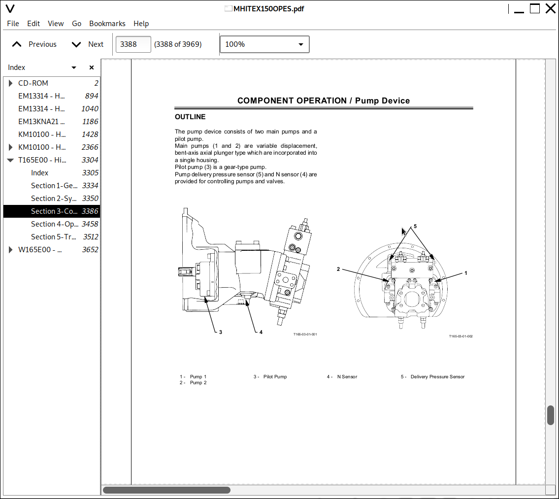
Hitachi EX150 EX150LC-5 EX160LC-5 Excavator Workshop Repair Manual + Operator's Manual PDF - MHITEX150OPES.zip
Hitachi EX150, EX150LC-5, EX160LC-5 Hydraulic Excavators Service Repair Manuals + Operator's Manuals
This all-inclusive service repair manual for the Hitachi EX150, EX150LC-5, and EX160LC-5 Hydraulic Excavators comes with complete electrical wiring diagrams, giving you every workshop detail needed to maintain, troubleshoot, and overhaul these machines just like a professional technician.
Hitachi Construction EX150, EX150LC-5, EX160LC-5 Hydraulic Excavators workshop service & repair manual includes:
* Numbered table of contents easy to use so that you can find the information you need fast.
* Detailed sub-steps expand on repair procedure information
* Numbered instructions guide you through every repair procedure step by step.
* Troubleshooting and electrical service procedures are combined with detailed wiring diagrams for ease of use.
* Notes, cautions and warnings throughout each chapter pinpoint critical information.
* Bold figure number help you quickly match illustrations with instructions.
* Detailed illustrations, drawings and photos guide you through every procedure.
* Enlarged inset helps you identify and examine parts in detail.
T165E00 - Hitachi EX150LC-5, EX160LC-5 Excavator Technical Manual
W165E00 - Hitachi EX150LC-5, EX160LC-5 Excavator Workshop Manual
EM13KNA21 - Hitachi EX160LC-5 Excavator Operator's Manual.pdf
EM13314 - Hitachi EX150 Excavator Operator's Manual.pdf
KM10100 - Hitachi EX150 Excavator Technical Manual (Service & Repair).pdf
EM13314 - Hitachi Excavator EX150 Operator's Manual.pdf
KM10100 - Hitachi Excavator EX150 Hydraulic Excavator Technical Service Manual.pdf
Total Pages: 3,951 pages
File Format: PDF (bookmarked, ToC, Searchable, Printable, high quality)
Language: English
MAIN SECTIONS
TABLE OF CONTENTS
GENERAL INFORMATION
UPPERSTRUCTURE
UNDERCARRIAGE
FRONT ATTACHMENT
ENGINE ASSEMBLY
MAINTENANCE
LUBRICATING SYSTEM
FUEL SYSTEM
TURBOCHARGER
AIR COMPRESSOR
ENGINE ELECTRICALS
TROUBLESHOOTING
...
CD-ROM.......2
EX150LC-5cir.......3
T165E-ELC1.......4
T165E-ELC2.......5
T165E-HARNESS1.......6
T165E-HARNESS2.......7
T165E-HARNESS3.......8
T165E-HARNESS4.......9
T165E-HYD.......10
TM.......11
INDEX.......12
Cover.......12
Introduction.......13
Safty.......15
T1.......41
CONTENTS(165T-1-1).......42
SECTION 1 GENERAL.......42
Group 1 Specification.......44
Specification.......44
Working Range and Machine Dimensions for Transportation.......45
Component Specifications.......46
Group 2 Component Layout.......52
Main Components.......52
Electrical System (Overall System).......53
Electrical System (Relays).......54
Electrical System (Monitor and Switch Panels).......55
Pump and Related Parts.......56
Other Components.......57
T2.......58
CONTENTS(165T-2-1).......59
SECTION 2 SYSTEM.......59
Group 1 Control System.......61
Outline.......61
Engine Control.......62
Pump Control.......68
Valve Control.......70
Other Control Function.......73
Group 2 Hydraulic System.......75
Main Circuit.......75
Pilot Circuit.......76
Neutral Circuit.......77
Single Actuator Operation.......77
Combined Operation.......78
Group 3 Electrical System.......81
Outline.......81
Electric Power Circuit.......82
Bulb Check Circut.......83
Preheat Circuit.......84
Starting Circuit.......86
Charging Circuit.......88
Surge Voltage Prevention Circuit.......91
Accessory Cirucuit.......92
Engine Stop Circuit.......93
T3.......95
CONTENTS(165T-3-1).......96
SECTION 3 COMPONENT OPERATION.......96
Group 1 Pump Device.......98
Outline.......98
Main Pump.......99
Regulator.......102
Pilot Pump.......110
N Sensor.......110
Pump Delevery Pressure Sensor.......110
Group 2 Swing Device.......112
Outline.......112
Swing Motor.......113
Valve Unit.......115
Swing Parking Brake.......117
Swing Reduction Gear.......118
Group 3 Control Valve.......120
Outline.......120
Hydraulic Circuit.......125
Flow Combiner Valve.......127
Pump Control Valve.......128
Main Relief Valve.......130
Overload Relief Valve.......130
Arm Regenerative Valve.......131
Boom Anti-Drift Valve, Arm Anti-Drift Valve.......133
Bucket Flow Control Valve.......133
Travel Flow Control Valve.......135
Travel/Boom lower Selector Valve.......135
Boom Regenerative Valve.......137
Group 4 Pilot Valve.......138
Outline.......138
Operation.......139
Group 5 Travel Device.......148
Outline.......148
Travel Reduction Gear.......149
Travel Motor.......150
Travel Brake Valve.......155
Parking Brake.......157
Group 6 Others (Upperstructure).......158
Pilot Shut-Off valve.......158
Shockless Valve.......159
Solenoid Valve Unit.......161
Pilot Relief Valve.......163
EC Motor.......163
Group 7 Others (Undercarriage).......164
Swing Bearing.......164
Center Joint.......165
Track Adjuster.......166
T4.......168
CONTENTS(165T-4-1).......169
SECTION 4 OPERATIONAL PERFORMANCE TEST.......169
Group 1 Introducution.......171
Operational Performance tests.......171
Preparation for Performance tests.......172
Group 2 Engine Test.......173
Engine Speed.......173
Engine Compression Pressure.......175
Valve Clearance Adjustment.......176
Nozzle Check.......178
Injection Timing.......180
Group 3 Excavator Test.......181
Travel Speed.......181
Track Revolution Speed.......182
Mistrack Check.......183
Travel Parking Function Check.......184
Swing Speed.......185
Swing Function Drift Check.......186
Swing Motor Leakage.......187
Swing Bearing Play.......188
Maximum Swingable Slant Angle.......189
Hydraulic Cylinder Cycle Time.......190
Dig Function Drift Check.......191
Control Lever Operating Force.......192
Control Lever Stroke.......193
Combined Boom Raise/Swing Function Check.......194
Group 4 Component Test.......195
Primary Pilot Pressure.......195
Secondary Pilot Pressure.......197
Solenoid Valve Set Pressure.......198
Main Pump Delivery Pressure.......200
Main Relief Valve Set Pressure.......201
Overload Relief Valve Set Pressure.......205
Main Pump Flow Test.......208
Swing Motor Drainage.......212
Travel Motor Drain Oil Pressure.......214
Group 5 Standard.......217
Operational Performance Standard Table.......217
Main Pump P-Q Diagram.......220
Injection Pump.......221
T5.......223
CONTENTS(165T-5-1).......224
SECTION 5 TROUBLESHOOTING.......224
Group 1 Diagnosing Procedure.......226
Introduction.......226
Diagnosing Procedure.......227
Dr.EX.......229
Dr.EX Start-Up Procedure.......229
Dr.EX Fault Code.......230
Dr.EX Monitoring Function.......231
Dr.EX Special Function (Service Mode).......232
Adjustable Data list.......239
Group 2 Component Layout.......240
Main Components.......240
Electrical System (Overall Syatem).......241
Electrical System (Relays).......242
Electrical System (Monitor and Switch Panels).......243
Pump and Related Parts.......244
Control Valve.......245
Others Components.......249
Group 3 Troubleshooting A.......250
Troubleshooting A Procedure.......250
Fault Codes.......251
Fault Code 01.......253
Fault Code 02, 03.......254
Fault Code 04, 05.......255
Fault Code 06.......256
Fault Code 07.......257
Sensor Operating Range List.......258
Group 4 Troubleshooting B.......260
Troubleshooting B Procedure.......260
Relationship Between Machine Trouble Symptoms and Parts in Trouble.......261
Correlation Between Trouble Symptoms and Part Failures.......271
Engine Troubleshooting.......277
Actuator Control Syatem Troubleshooting.......291
Front Attachment Control System Troubleshooting.......297
Swing System Troubleshooting .......309
Travel System Troubleshooting.......312
Troubleshooting for Other Functions.......317
Engine Speed Adjustment and Engine Learning.......319
Exchange Inspection Method.......320
Group 5 Troubleshooting C.......322
Traubleshooting C Procedure.......322
Malfunction of Coolant Temperature Gauge.......323
Malfunction of Fuel Gauge.......325
Malfunction of Indecator Light Check System.......327
Malfunction of Level Check Switch.......327
Malfunction of Engine Oil Level Indicator.......329
Malfunction of Coolant Level Indicator.......331
Malfunction of Hydraulic Oil Level INdicator.......333
Malfunction of Alternator Indicator.......335
Malfunction of Engine Oil Pressure Indicator.......337
Malfunction of Overheat Indicator.......339
Malfunction of Fuel Level Indicator.......341
Malfunction of Air Filter Restriction Indicator.......343
Malfunction of Buzzer.......345
Malfunction of Hour Meter.......347
Group 6 Electrical System Inspection.......348
Precautions for Inspection and Maintenace.......348
Instructions for Disconnecting Connectors.......350
Fuse Continuity Test.......351
Inspection and Replacement of Fusible Links.......352
Battery Voltage Check.......353
How to Troubleshoot Alternator Malfunctions.......354
Continuity Check.......355
Voltage and Current Check.......357
Replacement of Relay.......361
Group 7 Harness Check.......362
Circuit Check.......362
WM.......364
INDEX.......365
Cover.......365
Introduction.......366
Safty.......368
W1.......394
CONTENTS(165W-1-1).......395
SECTION 1 GENERAL INFORMATION.......395
Group 1 Precautions for Disassembling and Assembling.......397
Precautions for Disassembling and Assembling.......397
Maintenance Standard Terminology.......400
Group 2 Tightening Torque.......401
Tightening Torque Specifications.......401
Torqr Chart.......402
Piping Joint.......405
W2.......409
CONTENTS(165W-2-1).......410
SECTION 2 UPPERSTRUCTURE.......410
Group 1 Cab.......412
Remove and Install Cab.......412
Dimensions of the Cab Glass.......418
Group 2 Counterweight.......420
Remove and Install Couterweight.......420
Group 3 Main Frame.......422
Remove and Install Main Frame.......422
Group 4 Pump Device.......430
Remove and Install Pump Device.......430
Desassemble Pump Device.......433
Assemble Pump Device.......437
Disassemble Regulator Cover.......441
Assemble Regulator Cover.......443
Disassemble and Assemble Pilot Pump.......445
Group 5 Control Valve.......448
Remove and Install Control Valve.......448
Disassemble Control Valve 1.......451
Assemble Control Valve 1.......453
Disassemble Control Valve 2.......457
Assemble Control Valve 2-1.......461
Assemble Control Valve 2-2.......463
Disassemble Control Valve 3.......467
Assemble Control Valve 3.......469
Disassemble Control Valve 4.......473
Assemble Control Valve 4-1.......477
Assemble Control Valve 4-2.......481
Group 6 Swing Device.......484
Remove and Install Swing Device.......484
Disssemble Swing Device.......487
Assemble Swing Device.......491
Disassemble Swing Motor.......497
Assemble Swing Motor.......501
Maintenance Standard.......505
Group 7 Pilot Valve.......508
Remove and Install Right Pilot Valve.......508