
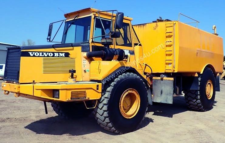
Volvo A20C Volvo BM Articulated Hauler Workshop Repair Service Manual PDF - MVLVCONA20C.zip
A full-service repair and maintenance manual, complete with electrical wiring schematics, for the Articulated Haulers A20C Volvo and A20C Volvo BM. It contains the technical data needed to maintain, troubleshoot, and service these machines to the standard of professional technicians.
The Volvo Construction Equipment Articulated Haulers A20C workshop service and repair manual covers:
* Numbered table of contents easy to use so that you can find the information you need fast.
* Detailed sub-steps expand on repair procedure information
* Numbered instructions guide you through every repair procedure step by step.
* Troubleshooting and electrical service procedures are combined with detailed wiring diagrams for ease of use.
* Notes, cautions and warnings throughout each chapter pinpoint critical information.
* Bold figure number help you quickly match illustrations with instructions.
* Detailed illustrations, drawings and photos guide you through every procedure.
* Enlarged inset helps you identify and examine parts in detail.
Articulated Haulers A20C Volvo Service Repair Manual.PDF
PRODUCT DETAILS:
Pages: 1,092
File Format: PDF (Windows & Mac & Linux)
Language: English
...
MAIN SECTIONS
0 - GENERAL
1 - STANDARD PARTS, SERVICE
2 - ENGINE WITH MOUNTING AND EQUIPMENT
3 - ELEC. SYSTEM; WARNING SYSTEM; INFORMATION SYSTEM; INSTRUMENTS
4 - POWER TRANSMISSION
5 - BRAKE
6 - STEERING
7 - FRAME; SPRINGS; DAMPING; AXLE SUSPENSION; WHEEL_TRACK UNIT
8 - MACHINERY HOUSE; CAB; EXTERIOR TRIM PARTS ANYWHERE
9 - HYDRAULIC SYSTEM; DIGGING_HANDLING_GRADING EQUIPM.; MISC EQUIPM
TABLE OF CONTENTS
0 - Foreword......1
0 - GENERAL......2
00 - DESCRIPTION; COMPLETE MACHINE......3
Description......3
Product identification plates......4
03 - SPECIFICATIONS......6
Brakes......6
Capacities......8
Dimensions......9
Electrical system......11
Engine......14
Hydraulic system......17
Power transmission-[4410]......19
Specifications, change intervals......22
Steering system......23
Tightening torques......24
Volvo standard tightening torques......34
Weights......36
07 - STANDARD TIME......38
Time Guide......38
08 - TOOL......47
Recycling station FRS-10GS......47
Special tools for the drivetrain......49
1 - STANDARD PARTS, SERVICE......53
16 - LUBRICANT; FUEL; OTHER FLUID......54
Brake system, changing brake fluid......54
Recommended lubricants......56
17 - SERVICE......58
Cleanliness, hydraulic systems......58
Electric welding......59
Repairs of hydraulic systems......60
Towing......61
2 - ENGINE WITH MOUNTING AND EQUIPMENT......63
21 - ENGINE......64
Compression check, engine at operating temperature......64
Description-......67
Engine and transmission, mounting......68
Engine and transmission, removing......72
Engine, mounting......81
Engine, removing......85
Specifications, capacities-[3020]......93
Specifications, general-[2652]......94
Specifications, general-[2853]......95
Specifications, tightening torques-[2409]......96
Specifications, tightening torques-[2441]......98
Specifications, tightening torques-[2512]......99
Specifications, tightening torques-[2543]......100
Specifications, tightening torques-[2718]......101
Specifications, weights-[2919]......102
Valves, adjusting......103
22 - LUBRICATING SYSTEM......105
Lubrication oil pressure, checking......105
Specifications, general-[2217]......107
Specifications, general-[2318]......108
23 - FUEL SYSTEM......109
Automatic timing adjuster (alpha adjuster)......109
Automatic timing adjuster, checking......110
Fuel feed pump, checking feed pressure......116
Fuel system, bleeding......118
Idle speed, checking and adjusting......120
Injection angle TDC, checking and adjusting......122
Injection angle, checking......127
Injectors, changing all......131
Low emission engines......135
Slow and fast idle speed, checking and......137
Specifications, capacities-[1912]......140
Specifications, general-[1219]......141
Specifications, general-[1456]......142
Specifications, general-[1943]......143
Specifications, tightening torques-[1246]......144
Specifications, tightening torques-[1523]......145
Stall speed, checking with service display unit......146
Stall speed, checking......148
25 - INLET & EXHAUST SYSTEM......149
Specifications, general-[0722]......149
Specifications, general-[0754]......150
Specifications, tightening torques-[0825]......151
26 - COOLING SYSTEM......152
Coolant filter, changing......152
Coolant, changing......154
Description-[0646]......157
Fan motor, changing piston rings......162
Hydraulic motor for fan or......168
Radiator fan drive, checking function of motor......170
Radiator fan drive, general description......172
Radiator fan motor, adjusting speed......174
Radiator, changing......176
Specifications, capacities-[0605]......178
Specifications, general-[0008]......179
Specifications, general-[0538]......181
Thermostat valve (removed), reconditioning......182
Thermostat valve, checking function......184
Thermostat valve, description......185
27 - ENGINE CONTROL......186
Throttle pedal, anti-throttle cylinder, adjusting......186
3 - ELECTRICAL; WARNING; INFORMATION; INSTRUMENTS......188
30 - GENERAL......189
Description-[5730]......189
Electrical symbols......190
Fuses......194
Special instructions for servicing the electrical system......208
31 - BATTERY......209
Charging of batteries......209
Specifications, general-[5437]......210
32 - ALTERNATOR; CHARGE REGULATOR......211
Alternator, changing......211
Charging, checking in machine (multimeter)......213
Specifications, general-[5212]......217
Specifications, general-[5243]......218
33 - STARTING SYSTEM......219
Specifications, general-[5136]......219
Starter motor, changing......220
35 - LIGHTING......223
Headlight assembly, changing 1 headlight incl. adjusting alignment......223
Headlights, adjusting against wall or wing......224
Specifications, general-[5011]......225
37 - CABLE; FUSE; RELAY......226
Additional fuses (serial no. 3101–)......226
Additional fuses (serial no. –3100)......228
Circuit 14–36 (cont'd.) (serial no. 3101–)......230
Circuit 14–36 (cont'd.) (serial no. –3100)......234
Circuit 14–36 (serial no. 3101–)......238
Circuit 14–36 (serial no. –3100)......242
Circuit 37a–37e (serial no. 3101–)......246
Circuit 37a–37e (serial no. –3100)......250
Circuit 37f–37I (serial no. 3101–)......254
Circuit 37f–37I (serial no. –3100)......258
Circuit 38–53A (serial no. 3101–)......262
Circuit 38–53A (serial no. –3100)......266
Circuit 53B–75 (contd.) (serial no. –3100)......270
Circuit 53B–75 (serial no. 3101–)......273
Circuit 53B–75 (serial no. –3100)......277
Circuit 66 and 77 (serial no. 3101–)......281
Circuit 66 and 77 (serial no. –3100)......285
Circuit 76–89 (serial no. 3101–)......288
Circuit 76–89 (serial no. –3100)......292
Circuit 7–13 (serial no. 3101–)......296
Circuit 7–13 (serial no. –3100)......300
Circuit 90–91 (serial no. –3100)......304
Circuit 90–93 (serial no. 3101–)......307
Circuit 94 and 98 (serial no. 3101–)......310
Circuit board, right electrical distribution box (serial no. 3101–)......314
Circuit board, right electrical distribution box (serial no. –3100)......315
Circuit index......316
Code legend for connectors-[3310]......319
Code legend for connectors......385
Codes in wiring diagrams......455
Explanations of wiring diagrams......456
Fuses, left electrical distribution box (serial no. 3101–)......458
Fuses, left electrical distribution box (serial no. –3100)......459
Fuses, right electrical distribution box (serial no. 3101–)......460
Fuses, right electrical distribution box (serial no. –3100)......463
Instrument panel, (serial no. 3101–)......466
Instrument panel, (serial no. –3100......468
Relays, left electrical distribution box (serial no. 3101–)......470
Relays, left electrical distribution box (serial no. –3100)......472
Relays, right electrical distribution box (serial no. 3101–)......474
Relays, right electrical distribution box (serial no. –3100)......477
Specifications, general-[1607]......479
Template for pin numbers connector X1_A1......480
Wiring diagrams, Circuit 0–6 (serial no. –3100)......482
Wiring diagrams......484
38 - INSTRUMENT; SENSOR; WARNING & INFORMATION SYSTEM......487
Connection......487
Contronic Information Display Unit......488
Contronic service display unit......490
ECU, reading off with measuring instrument......492
Information display unit, displays......494
Information display unit, summary......499
Information on the service display unit-[0634]......500
Information on the service display unit......511
Load sensor, adjusting......520
Load sensor, checking electric circuits-[1133]......522
Load sensor, checking electric circuits......525
Measuring instrument, summary......527
Service display unit, summary......528
Specifications, general-[1031]......529
Specifications, general-[1531]......530
Speedometer, electric, calibrating......531
Speedometer, electronic (serial no. 3066 –31498)......532
Speedometer, electronic programming instructions......534
Speedometer, electronic......539
Using the service display unit......543
4 - POWER TRANSMISSION......544
40 - GENERAL......545
41 - CLUTCH; TORQUE CONVERTER......547
42 - TRANSMISSION; HYDRAULIC CONTROL......548
43 - GEARBOX......622
45 - PROPELLER SHAFT......648
46 - FRONT AXLE; REAR AXLE......668
48 - POWER TAKE OFF......705
5 - BRAKE......719
50 - GENERAL......720
Description-[2706]......720
Specifications, general-[2634]......722
51 - WHEEL BRAKE......723
Brake caliper, changing (per caliper)......723
Brake caliper, reconditioning......727
Brake disc for service brake, checking......730
Brake disc, changing......732
Brake pads for service brake, checking......746
Brake pads, changing (one wheel)......748
Specifications, tightening torques-[2500]......754
Specifications, weights-[2435]......755
52 - HYDRAULIC BRAKE SYSTEM......756
Brake system, bleeding......756
Description-[2057]......759
Foot-brake valve......762
Specifications, capacities-[2024]......768
55 - PARKING BRAKE......769
Parking brake caliper removed, reconditioning......769
Parking brake valve – hand-operated lever......771
Parking brake valve, reconditioning......775
Parking brake, changing brake caliper......779
Parking brake, changing brake disc......783
Parking brake, changing brake pads......786
Parking brake......789
Specifications, general-[1407]......790
Specifications, general-[1530]......791
Specifications, tightening torques-[1602]......792
Spring brake cylinder removed, reconditioning......793
Spring brake cylinder, changing......796
56 - COMPRESSED-AIR BRAKE......798
Air compressor......798
Air-hydraulic unit......799
Anti-freeze reservoir......800
Automatic adjustment lever......802
Compressor, changing......804
Cut-out and cut-in pressures, checking and adjusting......807
Foot-brake valve, reconditioning (removed)......809
Four-way pressure retaining valve, reconditioning (removed)......813
Four-way pressure retaining valve......815
Pressure regulator repairs (removed)......819
Pressure regulator......821
Relay valve, reconditioning......823
Relay valve......825
Safety valve, wet tank......828
Specifications, capacities-[0634]......829
Specifications, capacities-[0819]......830
Specifications, general-[0359]......831
Specifications, general-[0609]......832
Specifications, general-[0728]......833
Specifications, general-[1151]......834
Specifications, tightening torques-[0753]......835
Spring brake cylinder......836
59 - MISCELLANEOUS......838
Compressed air diagram A20C (serial no. -3101) - Image......838
Compressed air diagram A20C (serial no. 3101-) - Image......839
Compressed air diagram A20C-[0328]......840
Compressed air diagram A20C......842
6 - STEERING......845
60 - GENERAL......846
Description, steering system......846
Specifications, general-[0148]......849
64 - STEERING......850
Damping cylinder, changing seals......850
Damping cylinder, checking pre-load......853
Damping cylinder, removing and mounting......855
Damping cylinder......857
Pressure accumulation, engine dependent pumps 1 and 2......858
Specifications, general-[0038]......861
Specifications, general-[4930]......862
Specifications, general-[5450]......863
Specifications, weights-[5516]......864
Steering cylinder bearing, checking......865
Steering cylinder, changing spherical bearing......867
Steering cylinder, changing......869
Steering cylinder, reconditioning in machine......872
Steering cylinder......876
Steering gear, changing......877
Steering gear, checking and adjusting......881
Steering linkage, changing roller bearing in front lever......884