
John Deere 9470STS 9570STS 9670STS 9770STS Combine Workshop Repair Manual (TM800219) PDF - MJODTM800219.zip
A full service and repair manual covering John Deere Combines and Headers models 9470 STS, 9570 STS, 9670 STS and 9770 STS (PIN Prefix CQ - South America), packed with the technical detail needed to maintain, troubleshoot and fix these machines just like a dealer technician.
Inside the John Deere 9770 STS, 9670 STS, 9570 STS and 9470 STS workshop service repair manual, you'll find:
* Numbered table of contents easy to use so that you can find the information you need fast.
* Detailed sub-steps expand on repair procedure information
* Numbered instructions guide you through every repair procedure step by step.
* Notes, cautions and warnings throughout each chapter pinpoint critical information.
* Bold figure number help you quickly match illustrations with instructions.
* Detailed illustrations, drawings and photos guide you through every procedure.
* Enlarged inset helps you identify and examine parts in detail.
TM800219 - John Deere Combines 9470STS, 9570STS, 9670STS, 9770STS Technical Manual - Repair.PDF
TM800219 - John Deere Combines 9470STS, 9570STS, 9670STS, 9770STS Technical Manual - Repair.EPUB
Total Pages: 2,030 pages
File Format: PDF/EPUB/MOBI/AZW (PC/Mac/Android/Kindle/iPhone/iPad; bookmarked, ToC, Searchable, Printable)
Language: English
MAIN SECTIONS
Foreword
General
Safety
Specifications
Tune-Up and Adjustment
Fuels And Lubricants
Engine
Remove And Install Engine
Cooling System
Fuel And Air Repair
Air Intake System
Diesel Fuel System
Electrical System
Batteries
Harness And Connector Repair
Wire Harness Routing
Power Distribution
Lighting
Operators Station
Sensors And Switches
Wiper
Alternator
Starting Motor
GreenStar Components
Power Train Repair
Transmission And Differential-Three Speed Transmission
Hydrostatic System-Three Speed Transmission
Single Reduction Final Drive-Heavy Duty
Cam Lobe Motor
Tires And Wheels
Power Steering And Brakes
Steering
Brakes
Hydraulic Repair
Hydraulic Reservoir
Hydraulic Pumps
Hydraulic Valves
Hydraulic Cylinders
Motors
Accumulator
Separator Shell
Gull Wing Doors
Operator Station Repair
Air Conditioning System (R134a)
System Components
Cab
Feeder House Repair
Conveyor
Top Shaft And Slip Clutch
Feeder House Drives And Reverser Gear Case
Lateral Tilt Cylinder
Lateral Tilt Frame
Separator
Separator Repair
Separator Drives
Residue Disposal
Conveyor Augers, Cleaning Fan And Chaffer And Sieve Frame
Tailings Elevator And Augers
Primary Countershaft Gear Case
Header Electromagnetic Clutch
Grain Tank And Unloading System Repair
Grain Tank Cross Augers
Unloading Auger System Drives
Vertical Unloading Auger And Lower Gear Case
Horizontal Unloading Auger And Gear Case
Clean Grain Elevator
Grain Tank And Extensions
Engine Gear Case And Control Valve Repair
Engine Gear Case And Valve
Dealer Fabricated Tools
Dealer Fabricated Tools
tm800219 - 9470 STS, 9570 STS, 9670 STS and 9770 STS Combine Repair
Table of Contents
Foreword
Section 10: General
Group 05: Safety
Recognize Safety Information
Understand Signal Words
Handle Fluids Safely—Avoid Fires
Prevent Battery Explosions
Handling Batteries Safely
Prepare for Emergencies
Prevent Acid Burns
Avoid High-Pressure Fluids
Service Accumulator Systems Safely
Wait Before Opening High-Pressure Fuel System
Park Machine Safely
Support Machine Properly
Wear Protective Clothing
Work in Clean Area
Service Machines Safely
Work In Ventilated Area
Illuminate Work Area Safely
Replace Safety Signs
Use Proper Lifting Equipment
Remove Paint Before Welding or Heating
Avoid Heating Near Pressurized Fluid Lines
Service Tires Safely
Avoid Harmful Asbestos Dust
Practice Safe Maintenance
Construct Dealer-Made Tools Safely
Use Proper Tools
Dispose of Waste Properly
Use Adequate Service Facilities
Live With Safety
Group 10: Specifications
Turning Radius
Operating Speeds — 9470 STS and 9570 STS Combines
Specifications — 9470 STS and 9570 STS Combines
Dimensions — 9470 STS and 9570 STS Combines
Dimension Reference Points — 9470 STS and 9570 STS Combines
Operating Speeds - 9670 STS, 9770 STS Combines
Specifications - 9670 STS Combine
Specifications - 9770 STS Combine
Dimensions — 9670 STS and 9770 STS Combines
Dimension Reference Points — 9670 STS and 9770 STS Combines
Metric Bolt and Screw Torque Values
Unified Inch Bolt and Screw Torque Values
Sealants and Adhesives Cross-Reference Chart
Face Seal Fittings Assembly and Installation—All Pressure Applications
Metric Face Seal And O-Ring Stud End Fitting Torque Chart—Standard Pressures
Metric Face Seal and O-Ring Stud End Fitting Torque Chart—High Pressure Applications
SAE Face Seal and O-Ring Stud End Fitting Torque Chart—Standard Pressures
SAE Face Seal and O-Ring Stud End Fitting Torque Chart—High Pressure Applications
Four Bolt Flange Fittings Assembly and Installation—All Pressure Applications
SAE Four Bolt Flange Cap Screw Torque Values—Standard Pressure Applications
SAE Four Bolt Flange Cap Screw Torque Values—High Pressure Applications
External Hexagon Port Plug Torque Chart
Prevent Hydraulic System Contamination
Check Oil Lines and Fittings
Basic Electrical Component Handling / Precautions For Vehicles Equipped With Computer Controlled Systems
Group 15: Tune-Up and Adjustment
Tune-Up and Adjustment
Care and Maintenance of Belts
Defective Belts
Group 20: Fuels And Lubricants
Handle Fuel Safely—Avoid Fires
Handling and Storing Diesel Fuel
Diesel Fuel
Biodiesel Fuel
Lubricity of Diesel Fuel
Testing Diesel Fuel
Heavy Duty Diesel Engine Coolant
Operating in Warm Temperature Climates
Supplemental Coolant Additives
Additional Information About Diesel Engine Coolants and John Deere LIQUID COOLANT CONDITIONER
Testing Diesel Engine Coolant
Diesel Engine Break-In Oil
Diesel Engine Oil
Oilscan™ and CoolScan™
Hydrostatic Drive System, Main Hydraulic System and Main Engine Gearcase Oils
Transmission, Final Drives, Loading Auger, Primary Countershaft and Two-Speed Separator Drive Gear Cases
Feeder House Reverser Gear Case
Grease
Brake Fluid
Lubricant Storage
Alternative and Synthetic Lubricants
Mixing of Lubricants
Section 20: Engine
Group 05: Remove And Install Engine
Special Tools
Specifications
John Deere Engine Repair—Use CTM
Remove Engine—6.8 L
Install Engine—6.8 L
Remove Engine—9.0 L
Install Engine—9.0 L
Group 10: Cooling System
Special Tools
Specifications
John Deere Engine Repair—Use CTM
Rotary Screen Drive
Rotary Screen Idler Arm and Sheaves
Remove and Install Upper and Lower Air Scoops
Remove and Install Rotary Screen
Adjusting Rotary Screen Knife Comb
Remove Radiator—6.8 L Engine
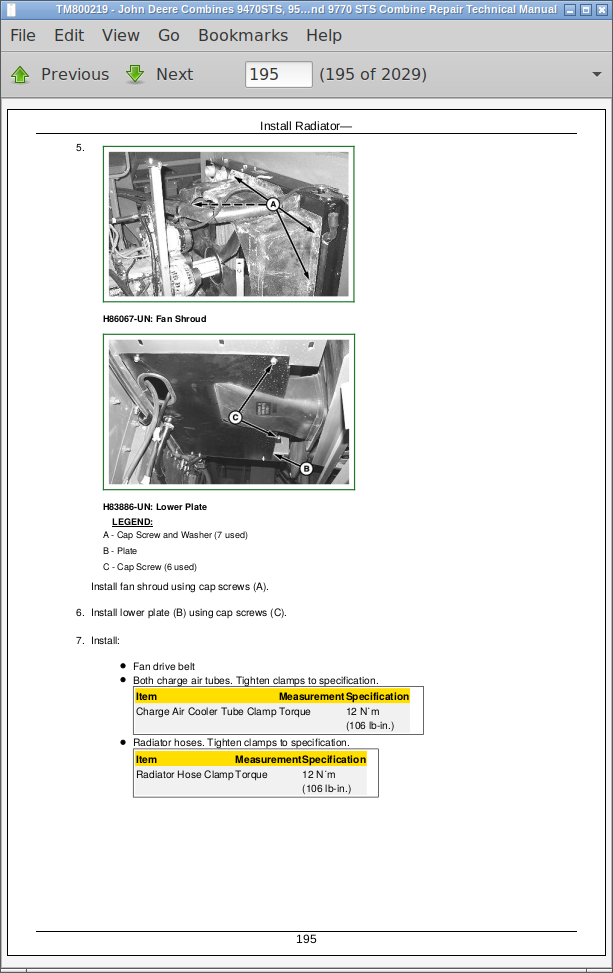
Install Radiator—6.8 L Engine
Remove Radiator—9.0 L Engine
Install Radiator—9.0 L Engine
Test Radiator
Test Radiator Cap
Replace Thermostats
Repair or Replace Water Pump
Section 30: Fuel And Air Repair
Group 05: Air Intake System
Other Material
Specifications
John Deere Engine Repair—Use CTM
Remove and Install Turbocharger
Turbocharger Repair
Remove and Install Charge Air Cooler
Cleaning the Charge Air Cooler
Group 10: Diesel Fuel System
Other Material
Specifications
Remove and Install Fuel Tank
Remove and Install Fuel Tank Shut-Off Valve and Drain Valve—9570, 9670, and 9770
Remove and Install Fuel Tank Strainer and Breather
Section 40: Electrical System
Group 05: Batteries
Prevent Battery Explosions
Prevent Damage to Electrical Systems
Battery Replacement
Remove and Install Batteries
Connecting Booster Batteries
Connecting Battery Cables
Group 10: Harness And Connector Repair
Special Tools
Other Material
Use Electrical Insulating Compound
Using High-Pressure Washers
Electrical System Visual Inspection
Basic Electrical Component Handling / Precautions for Vehicles Equipped with Computer Controlled Systems
Electrical Connector / Wiring Harness Handling and Repair
Repair Procedure R-A
Repair Procedure R-B
Repair Procedure R-C
Repair Procedure R-D
Repair Procedure R-E
Repair Procedure R-F
Repair Procedure R-G
Repair Procedure R-I
Repair Procedure R-J
Repair Procedure R-K
Repair Procedure R-M
Repair Procedure R-N
Repair Procedure R-AE
Repair Procedure R-AF
Repair Procedure R-AG
Repair Procedure R-AH
Repair Procedure R-AI
Repair Procedure R-AJ
Repair Procedure R-AK
Repair Procedure R-AL
Group 15: Wire Harness Routing
Replace Harness
Cab Main Wiring Harness
Left-Hand Main Wiring Harness
LC1 Wiring Harness
LC2 Wiring Harness
Self-Leveling Shoe Wiring Harness
Right-Hand Main Wiring Harness
Engine Deck Wiring Harness—6.8 L and 9.0 L
Group 20: Power Distribution
Fuse Identification
Remove and Install Cab Power Module (CPM)
Remove and Install Right and Left Power Modules
Group 25: Lighting
Safety Rules When Replacing Halogen Bulbs
Cab Head Light Bulb Replacement and Adjustment
Remove and Install High Intensity Discharge (HID-Xenon) Lights (Optional)
Remove and Install High Intensity Discharge (HID-Xenon) Ballasts
Auxiliary Field, Access Door, Grain Tank, Unload Auger and Work Light Bulb Replacement
Side Finder (Optional) Light Bulb Replacement
Front Turn Signal, Tail and Side Light Bulb Replacement
Harzard/Warning Light Bulb Replacement
Cleaning Shoe Light Bulb Replacement
Turn Signal Light Bulb Replacement
Dome Light Bulb Replacement
Group 30: Operators Station
Other Material
Specifications
Instruments And Controls Identification
Remove and Install Overhead Panel
Remove and Install Right-Hand Overhead Panel
Remove and Install Light Panel Dimmer Switch
Remove and Install Overhead Panel and Right-Hand Overhead Panel Rocker Switches
Remove and Install ClimaTrak ClimaTrak is a trademark of Deere & Company Automatic Air Conditioning/Heater Temperature Control Switch and Fan Switch
Remove and Install Radio Antenna
Replace Cornerpost Main Circuit Board
Remove Header Control Module
Remove VisionTrak VisionTrak is a trademark of Deere & Company Module and Digital Tachometer Module
CommandTouch Console Controls
Remove and Install CommandTouch Console
Remove and Install Armrest Display Unit
Remove and Install Header and Separator Engage Switches
Remove and Install Backlighting Driver
Remove and Install Dial-A-Speed and Active Header Control Switches
Remove and Install CommandTouch Console Switch Panel
Replace Neutral Safety Switch
Remove and Install Multi-Function Handle
Remove and Install Start Switch
Remove and Install Turn Signal/Side Finder Light Switch
Remove and Install Horn Switch