
John Deere 4730 Self-Propelled Sprayer Repair & Diagnostic Manual (TM802419) Pin 1NW - MJODTM802419.zip
A full Operation and Test guide featuring Electrical Wiring Diagrams for the John Deere 4730 Self-Propelled Sprayer (Brazil market, PIN Prefix 1NW), delivering the same workshop-level detail professionals rely on to maintain, troubleshoot, and repair the machine.
Inside the John Deere 4730 Self-Propelled Sprayer Operation and Test manual, you'll find:
* Numbered table of contents easy to use so that you can find the information you need fast.
* Detailed sub-steps expand on repair procedure information
* Numbered instructions guide you through every repair procedure step by step.
* Troubleshooting and electrical service procedures are combined with detailed wiring diagrams for ease of use.
* Notes, cautions and warnings throughout each chapter pinpoint critical information.
* Bold figure number help you quickly match illustrations with instructions.
* Detailed illustrations, drawings and photos guide you through every procedure.
* Enlarged inset helps you identify and examine parts in detail.
TM802419 - John Deere 4730 Self-Propelled Sprayers Technical Manual (Operation and Test).PDF
TM802419 - John Deere 4730 Self-Propelled Sprayers Technical Manual (Operation and Test).EPUB
Total Pages: 3,332 pages
File Format: PDF/EPUB/MOBI/AZW (PC/Mac/Android/Kindle/iPhone/iPad; bookmarked, ToC, Searchable, Printable)
Language: English
MAIN SECTIONS
Diagnostic Trouble Codes (DTC)
BHC - Boom Hydraulic Controller (DTC)
CCU - Chassis Control Unit (DTC)
ECU - Engine Control Unit (DTC)
iTC - Integrated Terrain Compensation (DTC)
SRC - Spray Rate Controller (DTC)
SSU - Steering System Unit (DTC)
TEC - Tractor Equipment Control (DTC)
TEI - Tractor Equipment Interface (DTC)
Engine
Air Intake and Cooling System
Electrical
General Information - Electrical Section
Accessing Diagnostic Codes and Addresses
Calibration Procedures
Diagnostic Trouble Codes
Diagnostic Addresses
Boom
- BoomTrac Pro Leveling System
- Leveling (Left-hand Side)
- Leveling (Right-hand Side)
- Raise/Lower
- Return to Height
- Roll/Bias
- Unfold/Fold
Cab
- Air Conditioning System
- Auxiliary Power Outlets
- Horn
- Windshield Wiper
CAN Bus
- Communications
- Multifunction Control Handle
Engine
- Air Filter Switch
- Coolant Temperature Sensor
- Engine and Fuel Controls
- Oil Pressure Sensor
- Speed Sensors
- Throttle Controls
- Fuel Level Sensor
GreenStar
- AutoTrac
- Display
- Receiver
Hydraulics
- Oil Temperature Sensor
- Ladder
- Load Sense Jam Valve
- Tread Adjust
Lighting System
- Dome and Entry Lights
- Field, Road, Warning, and Turn Signal Lights
Operator Presence Switch
Operator Warning Lights
- Caution Light
- Stop Light
Power Distribution
Power Train
- Backup Alarm
- Drivetrain Status
- Hydrostatic Boost
- Park Brake
- Speed Range Controls
- Traction Control
- Wheel Speed Sensors
Radar Sensor
Solution System
- Agitation
- Solution Pressure
- Solution Pump
- Spray Valve Control
- Spray Rate
- Charging System
Starting and Charging - Starting System
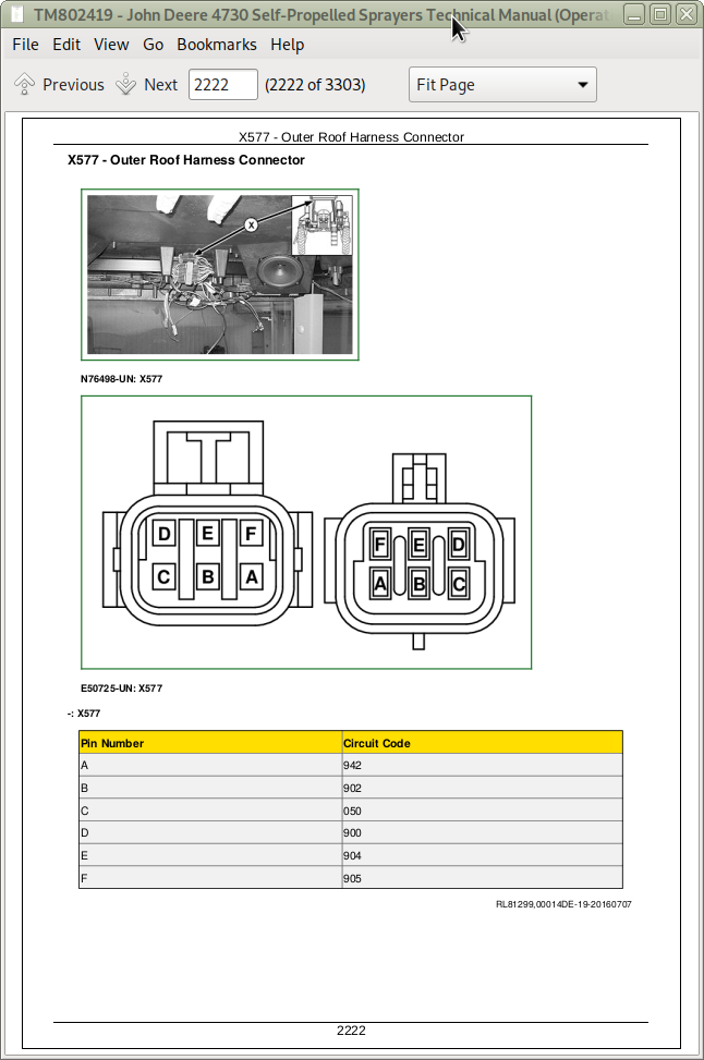
Connector Information (end views, numbers, location photos)
Power Train
Brakes
Hydraulics
Suspension and Tread Adjust
Steering
Operator Station
Solution System
Automatic Air Suspension Leveling System
Service Tools
tm802419 - 4730 Self-Propelled Sprayer — Diagnostic Technical Manual -: (South America Edition)
Table of Contents
Foreword
Section 210: General Information
Group 05: Safety
Recognize Safety Information
Understand Signal Words
Perform Service Safely
Wait Before Opening High-Pressure Fuel System
Service Accumulator Systems Safely
Handle Fluids Safely—Avoid Fires
Prevent Battery Explosions
Prepare for Emergencies
Protect Against High Pressure Spray
Prevent Acid Burns
Wear Protective Clothing
Handle Agricultural Chemicals Safely
Service and Operate Chemical Sprayers Safely
Avoid Contact with Agricultural Chemicals
Clean Vehicle of Hazardous Pesticides
Support Machine Properly
Service Machines Safely
Practice Safe Maintenance
Avoid Harmful Asbestos Dust
Work In Ventilated Area
Work in Clean Area
Remove Paint Before Welding or Heating
Avoid Heating Near Pressurized Fluid Lines
Avoid High-Pressure Fluids
Service Tires Safely
Service Cooling System Safely
Illuminate Work Area Safely
Replace Safety Signs
Use Proper Lifting Equipment
Use Proper Tools
Construct Dealer-Made Tools Safely
Decommissioning — Proper Recycling and Disposal of Fluids and Components
Live With Safety
Section 211: Diagnostic Trouble Codes
Group BHC: Boom Hydraulic Controller
BHC 000158.00 - Switched Supply Voltage High
BHC 000158.01 - Switched Supply Voltage Low
BHC 000237.02 - VIN Security Data Conflict
BHC 000237.14 - VIN Security Not Enabled
BHC 000237.31 - VIN Security Messages Missing
BHC 000628.12 - Programming
BHC 000629.12 - Control Unit Fault
BHC 000630.02 - Calibration Fault/Data Invalid
BHC 000639.14 - CAN Error - Limit Exceeded
BHC 001231.14 - CAN 2 Error Limit Exceeded
BHC 002065.14 - PVT Missing
BHC 002071.09 - ECU Message Missing
BHC 002170.09 - BHC Sensor Missing
BHC 522316.03 - Boom Center Frame Height Sensor Voltage is Above Normal
BHC 522316.04 - Boom Center Frame Height Sensor Voltage is Below Normal
BHC 522316.13 - Boom Center Frame Height Sensor is Out of Calibration
BHC 522372.13 - Right Hand Inner Calibration
BHC 522377.13 - Right Hand Outer Calibration
BHC 522378.13 - Left Hand Inner Calibration
BHC 522380.13 - Left Hand Outer Calibration
BHC 523461.03 - Roll Bias Sensor High
BHC 523461.04 - Roll Bias Sensor Low
BHC 523461.13 - Boom Roll Bias Sensor Out of Calibration
BHC 523463.05 - Roll Bias Left Coil Current Low
BHC 523463.06 - Roll Bias Left Coil Current High
BHC 523464.05 - Roll Bias Right Coil Current Low
BHC 523464.06 - Roll Bias Right Coil Current High
BHC 523477.05 - Center Frame Lower Coil Current is Below Normal or Open Circuit
BHC 523477.06 - Center Frame Lower Coil Current is Above Normal or Short Circuit
BHC 523478.05 - Center Frame Raise Coil Current is Below Normal or Open Circuit
BHC 523478.06 - Center Frame Raise Coil Current is Above Normal or Short Circuit
BHC 523479.05 - Left Boom Tilt Down Coil Current is Below Normal or Open Circuit
BHC 523479.06 - Left Boom Tilt Down Raise Coil Current is Above Normal or Short Circuit
BHC 523480.05 - Right Boom Tilt Down Coil Current is Below Normal or Open Circuit
BHC 523480.06 - Right Boom Tilt Down Raise Coil Current is Above Normal or Short Circuit
BHC 523481.05 - Left Boom Tilt Up Coil Current is Below Normal or Open Circuit
BHC 523481.06 - Left Boom Tilt Up Raise Coil Current is Above Normal or Short Circuit
BHC 523482.05 - Right Boom Tilt Up Coil Current is Below Normal or Open Circuit
BHC 523482.06 - Right Boom Tilt Up Raise Coil Current is Above Normal or Short Circuit
Group CCU: Chassis Control Unit
CCU 000070.02 - Park Brake Switch Fault
CCU 000096.01 - Fuel Level Low
CCU 000096.05 - Fuel Sensor Circuit Open
CCU 000096.06 - Fuel Sensor Circuit Closed
CCU 000158.00 - CCU-SRC Switched Supply Voltage High
CCU 000158.01 - CCU-SRC Switched Supply Voltage Low
CCU 000237.02 - VIN Data Does Not Match Other Controllers
CCU 000237.14 - VIN Security Not Enabled
CCU 000237.31 - VIN Messages Missing
CCU 000628.12 - CCU Programming
CCU 000629.12 - CCU Control Unit Fault
CCU 000630.02 - CCU Calibration Fault/Data Invalid
CCU 000639.14 - CCU CAN 1 Message Overflow
CCU 001231.14 - CCU CAN 2 Message Overflow
CCU 001504.02 - Operator Seat Switch Fault
CCU 001592.02 - Left Front Wheel Speed Sensor Frequency Invalid
CCU 002000.09 - ECU Message Missing
CCU 002246.09 - Multifunction Control Handle Message Missing
CCU 524279.31 - Operator Out of Seat
Group ECU14: Engine Control Unit
ECU 000091.09 - Throttle Communication Signal Erratic
ECU 000097.03 - Water-in-Fuel Signal Out of Range High
ECU 000097.04 - Water-in-Fuel Signal Out of Range Low
ECU 000097.16 - Water in Fuel Detected
ECU 000100.01 - Engine Oil Pressure Signal Extremely Low
ECU 000100.03 - Engine Oil Pressure Signal Out of Range High
ECU 000100.04 - Engine Oil Pressure Signal Out of Range Low
ECU 000100.18 - Engine Oil Pressure Signal Moderately Low
ECU 000100.31 - Engine Oil Pressure Invalid
ECU 000102.02 - Intake Manifold Pressure Signal Invalid
ECU 000102.03 - Intake Manifold Pressure Signal Out of Range High
ECU 000102.04 - Intake Manifold Pressure Signal Out of Range Low
ECU 000103.00 - Turbo Speed Signal Extremely High
ECU 000103.02 - Turbo Speed Signal Invalid
ECU 000103.05 - Turbo Speed Sensor Circuit has High Resistance
ECU 000103.06 - Turbo Speed Sensor Circuit has Low Resistance
ECU 000103.08 - Turbocharger Speed Signal Invalid
ECU 000103.31 - TurboCharger Speed Signal Missing
ECU 000105.00 - Intake Manifold Air Temperature Signal Extremely High
ECU 000105.03 - Intake Manifold Air Temperature Signal Out of Range High
ECU 000105.04 - Intake Manifold Air Temperature Signal Out of Range Low
ECU 000105.15 - Intake Manifold Air Temperature Signal Slightly High
ECU 000105.16 - Intake Manifold Air Temperature Signal Moderately High
ECU 000107.00 - Air Filter Differential Pressure High
ECU 000108.02 - Barometric Pressure Signal Invalid
ECU 000110.00 - Engine Coolant Temperature Signal Extremely High
ECU 000110.03 - Engine Coolant Temperature Signal Out of Range High
ECU 000110.04 - Engine Coolant Temperature Signal Out of Range Low
ECU 000110.15 - Engine Coolant Temperature Signal Slightly High
ECU 000110.16 - Engine Coolant Temperature Signal Moderately High Diagnostic Procedure
ECU 000110.17 - Engine Coolant Temperature Signal Slightly Low
ECU 000157.03 - Fuel Rail Pressure Signal Out of Range High
ECU 000157.04 - Fuel Rail Pressure Signal Out of Range Low
ECU 000157.10 - Fuel Rail Pressure Rate of Change Abnormal
ECU 000157.17 - Fuel Rail Pressure Not Developed
ECU 000158.17 - ECU Power Down Error
ECU 000174.00 - Fuel Temperature Signal Extremely High
ECU 000174.03 - Fuel Temperature Signal Out of Range High
ECU 000174.04 - Fuel Temperature Signal Out of Range Low
ECU 000174.16 - Fuel Temperature Signal Moderately High
ECU 000189.00 - Engine Speed Derate Condition Exists
ECU 000190.00 - Engine Speed Extremely High
ECU 000412.00 - EGR Temperature Signal Extremely High
ECU 000412.03 - EGR Temperature Signal Out of Range High
ECU 000412.04 - EGR Temperature Signal Out of Range Low
ECU 000412.16 - EGR Temperature Signal Moderately High
ECU 000611.03 - Injector Shorted to Power
ECU 000611.04 - Injector Shorted to Ground
ECU 000627.01 - Injector Pull In Current Too Low or Hold Current Incorrect
ECU 000629.12 - Bad Intelligent Device or Component
ECU 000629.13 - ECU Programming Error
ECU 000636.02 - Pump Position Sensor Signal Invalid
ECU 000636.05 - Pump Position Sensor Circuit Has High Resistance
ECU 000636.06 - Pump Position Sensor Circuit Has Low Resistance
ECU 000636.08 - Pump Position Sensor Signal Missing
ECU 000636.10 - Pump Position Signal Rate of Change Abnormal
ECU 000637.02 - Crank Sensor Signal Invalid
ECU 000637.05 - Crank Sensor Circuit Has High Resistance
ECU 000637.06 - Crank Sensor Circuit Has Low Resistance
ECU 000637.07 - Crank and Pump Position Signals Out of Sync
ECU 000637.08 - Crank Sensor Signal Missing
ECU 000637.10 - Crank Signal Rate of Change Abnormal
ECU 000641.04 - VGT Actuator Supply Voltage Out of Range Low
ECU 000641.12 - VGT Actuator Communication Error
ECU 000641.13 - VGT Actuator Learn Error
ECU 000641.16 - Turbo Actuator Temperature Moderately High
ECU 000651.02 - Injector Number 1 Part Number Data Invalid
ECU 000651.05 - Injector Number 1 Circuit Has High Resistance
ECU 000651.06 - Injector Number 1 Circuit Has Low Resistance
ECU 000651.07 - Injector Number 1 Not Responding
ECU 000651.13 - Injector Number 1 Calibration Fault
ECU 000652.02 - Injector Number 2 Part Number Data Invalid
ECU 000652.05 - Injector Number 2 Circuit Has High Resistance
ECU 000652.06 - Injector Number 2 Circuit Has Low Resistance
ECU 000652.07 - Injector Number 2 Not Responding
ECU 000652.13 - Injector Number 2 Calibration Fault
ECU 000653.02 - Injector Number 3 Part Number Data Invalid
ECU 000653.05 - Injector Number 3 Circuit Has High Resistance
ECU 000653.06 - Injector Number 3 Circuit Has Low Resistance
ECU 000653.07 - Injector Number 3 Not Responding
ECU 000653.13 - Injector Number 3 Calibration Fault
ECU 000654.02 - Injector Number 4 Part Number Data Invalid
ECU 000654.05 - Injector Number 4 Circuit Has High Resistance
ECU 000654.06 - Injector Number 4 Circuit Has Low Resistance
ECU 000654.07 - Injector Number 4 Not Responding
ECU 000654.13 - Injector Number 4 Calibration Fault
ECU 000655.02 - Injector Number 5 Part Number Data Invalid
ECU 000655.05 - Injector Number 5 Circuit Has High Resistance
ECU 000655.06 - Injector Number 5 Circuit Has Low Resistance
ECU 000655.07 - Injector Number 5 Not Responding
ECU 000655.13 - Injector Number 5 Calibration Fault
ECU 000656.02 - Injector Number 6 Part Number Data Invalid
ECU 000656.05 - Injector Number 6 Circuit Has High Resistance
ECU 000656.06 - Injector Number 6 Circuit Has Low Resistance
ECU 000656.07 - Injector Number 6 Not Responding
ECU 000656.13 - Injector Number 6 Calibration Fault
ECU 000676.03 - Glow Plugs Signal Received When Not Expected
ECU 000676.04 - Glow Plugs Signal Not Received When Expected
ECU 001136.00 - ECU Temperature Signal Extremely High