
John Deere 470GLC Excavator Workshop Repair Service Manual TM13174X19 PDF - MJODTM13174X19.zip
The full factory service and repair guide for the John Deere 470GLC Excavator (PIN: 1FF470GX__C047001-), packed with everything a workshop needs to service, fix, and overhaul the machine at a professional level.
Contained within the John Deere 470GLC workshop service & repair manual:
* Numbered table of contents easy to use so that you can find the information you need fast.
* Detailed sub-steps expand on repair procedure information
* Numbered instructions guide you through every repair procedure step by step.
* Notes, cautions and warnings throughout each chapter pinpoint critical information.
* Bold figure number help you quickly match illustrations with instructions.
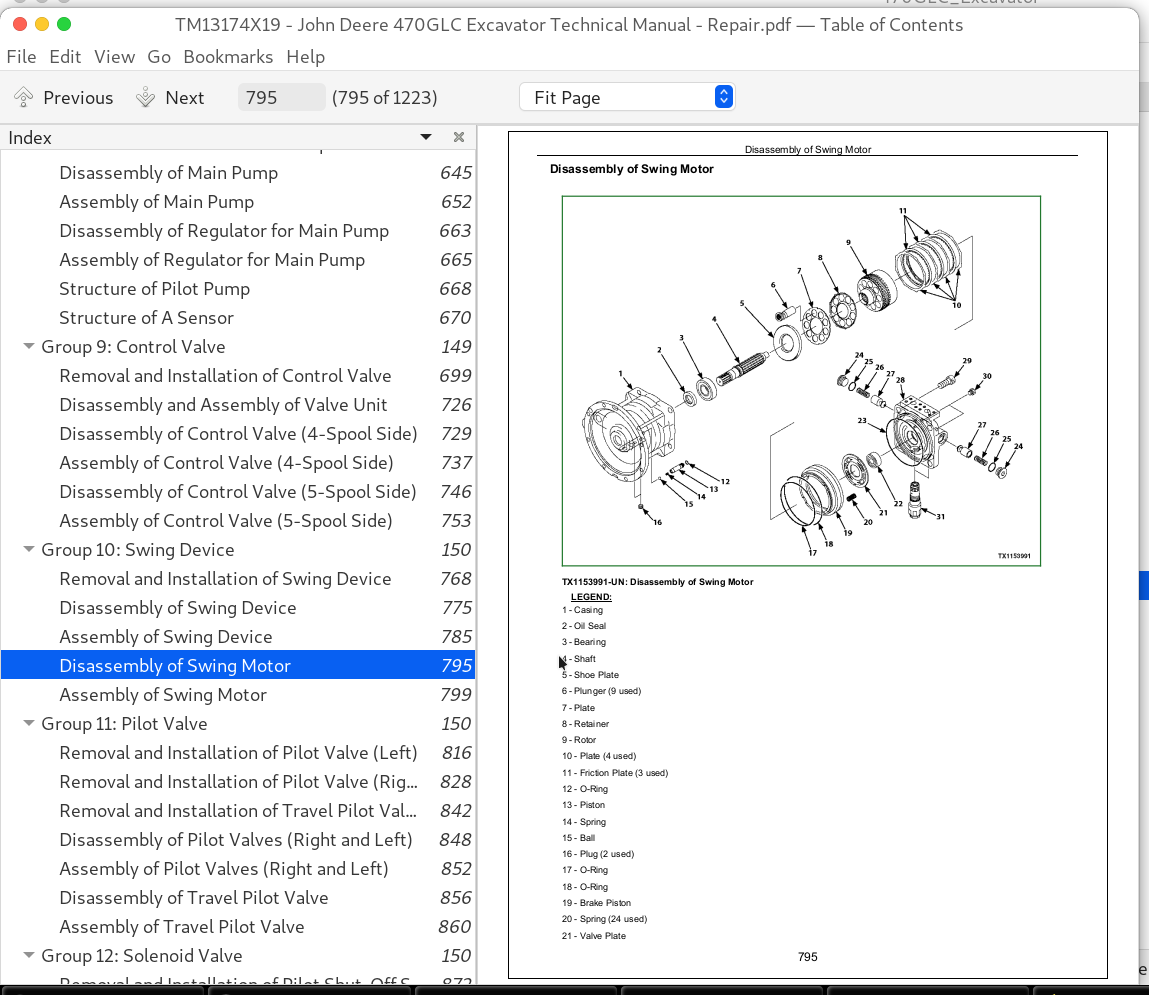
* Detailed illustrations, drawings and photos guide you through every procedure.
* Enlarged inset helps you identify and examine parts in detail.
TM13174X19 - John Deere 470GLC Excavator Technical Manual - Repair.PDF
tm13174x63 - 470GLC Excavadora Taller.pdf
tm13174x54 - Escavadeira 470GLC Oficina (PIN: 1FF470GX_ _C047001— ).pdf
PRODUCT DETAILS:
Total Pages: 1,223 pages
File Format: PDF (bookmarked, ToC, Searchable, Printable, high quality)
Language: English Portuguese Spanish
Model: John Deere - 470GLC Excavator - 1FF470GX__C047001
MAIN SECTIONS
To The Reader
Additional References
Manual Composition
Page Number
Safety Alert Symbol and Headline Notations
Units Used
Symbol and Abbreviation
Safety
Safety
General Information
Precautions for Disassembling and Assembling
Tightening
Bleeding Air
Pressure Release Procedure
Preparation
Maintenance Standard
Upperstructure
Undercarriage
Front Attachment
Upperstructure
Cab
Counterweight
Main Frame
Engine
Radiator Assembly
Hydraulic Oil Tank
Fuel Tank
Pump Device
Control Valve
Swing Device
Pilot Valve
Solenoid Valve
Signal Control Valve
Shockless Valve
Undercarriage
Swing Bearing
Travel Device
Center Joint
Track Adjuster
Front Idler
Upper and Lower Rollers
Track
Front Attachment
Front Attachment
Cylinder
TABLE OF CONTENTS................1
Section Safety: Safety................16
Group : Safety................16
Recognize Safety Information................19
Follow Safety Instructions................20
Operate Only If Qualified................21
Wear Protective Equipment................22
Avoid Unauthorized Machine Modifications................23
Add Cab Guarding for Special Uses................24
Inspect Machine................25
Stay Clear of Moving Parts................26
Avoid High-Pressure Fluids................27
Avoid High-Pressure Oils................28
Work In Ventilated Area................29
Prevent Fires................30
Prevent Battery Explosions................31
Handle Chemical Products Safely................32
Dispose of Waste Properly................33
Prepare for Emergencies................34
Clean Debris from Machine................35
Use Steps and Handholds Correctly................36
Start Only From Operator's Seat................37
Use and Maintain Seat Belt................38
Prevent Unintended Machine Movement................39
Avoid Work Site Hazards................40
Keep Riders Off Machine................42
Avoid Backover Accidents................43
Inspect and Maintain ROPS................44
Avoid Machine Tip Over................45
Use Special Care When Lifting Objects................47
Add and Operate Attachments Safely................48
Park and Prepare for Service Safely................49
Service Cooling System Safely................50
Remove Paint Before Welding or Heating................51
Make Welding Repairs Safely................52
Drive Metal Pins Safely................53
MEMO................1220
Section W1: General Information................56
Group 1: Precautions for Disassembling and Assembling................64
Precautions for Disassembling and Assembling................64
Group 2: Tightening................56
Metric Bolt and Cap Screw Torque Values................76
Piping Joint................81
Group 4: Bleeding Air................56
Bleeding Air from Hydraulic Oil Tank................92
Bleeding Air from Hydraulic System................94
Bleeding Air from Fuel System................95
Bleeding Air from Radiator................97
Group 5: Pressure Release Procedure................56
Hydraulic Circuit Pressure Release Procedure................99
Group 6: Preparation................56
Preparation before Inspection and Maintenance................101
MEMO................1220
MEMO................1220
Section W2: Maintenance Standard................106
Group 1: Upperstructure................106
Main Pump................110
Swing Motor................113
Group 2: Undercarriage................106
Travel Motor................119
Sprocket................121
Center Joint................122
Front Idler................124
Upper Roller................126
Lower Roller................127
Track................128
Group 3: Front Attachment................106
Remove and Install Bushing................134
Pin and Bushing................136
Side Cutter................138
Point................139
Standard Dimensions for Arm and Bucket Connection................140
Standard Dimensions for Arm and Boom Connection................142
Cylinder................143
MEMO................1220
MEMO................1220
Section W3: Upperstructure................149
Group 1: Cab................149
Removal and Installation of Cab................183
Windshield Remove and Install................214
Windshield Disassemble and Assemble................216
Sliding Windows Remove and Install................226
Windowpanes Remove and Install................228
Windowpanes Dimensions................229
Group 2: Counterweight................149
Removal and Installation of Counterweight................244
Group 3: Main Frame................149
Removal and Installation of Main Frame................260
Group 4: Engine................149
Removal and Installation of Engine................334
Group 5: Radiator Assembly................149
Replacement of Radiator and Oil Cooler................436
Group 6: Hydraulic Oil Tank................149
Removal and Installation of Hydraulic Oil Tank................500
Group 7: Fuel Tank................149
Removal and Installation of Fuel Tank................548
Group 8: Pump Device................149
Removal and Installation of Pump Device................607
Disassembly of Main Pump................645
Assembly of Main Pump................652
Disassembly of Regulator for Main Pump................663
Assembly of Regulator for Main Pump................665
Structure of Pilot Pump................668
Structure of A Sensor................670
Group 9: Control Valve................149
Removal and Installation of Control Valve................699
Disassembly and Assembly of Valve Unit................726
Disassembly of Control Valve (4-Spool Side)................729
Assembly of Control Valve (4-Spool Side)................737
Disassembly of Control Valve (5-Spool Side)................746
Assembly of Control Valve (5-Spool Side)................753
Group 10: Swing Device................150
Removal and Installation of Swing Device................768
Disassembly of Swing Device................775
Assembly of Swing Device................785
Disassembly of Swing Motor................795
Assembly of Swing Motor................799
Group 11: Pilot Valve................150
Removal and Installation of Pilot Valve (Left)................816
Removal and Installation of Pilot Valve (Right)................828
Removal and Installation of Travel Pilot Valve................842
Disassembly of Pilot Valves (Right and Left)................848
Assembly of Pilot Valves (Right and Left)................852
Disassembly of Travel Pilot Valve................856
Assembly of Travel Pilot Valve................860
Group 12: Solenoid Valve................150
Removal and Installation of Pilot Shut-Off Solenoid Valve................872
Removal and Installation of 4-Spool Solenoid Valve Unit................877
Removal and Installation of 2-Spool Solenoid Valve Unit................883
Disassembly of Pilot Shut-Off Solenoid Valve................888
Assembly of Pilot Shut-Off Solenoid Valve................890
Structure of 4-Spool Solenoid Valve Unit................892
Structure of 2-Spool Solenoid Valve Unit................894
Group 13: Signal Control Valve................150
Removal and Installation of Signal Control Valve................905
Structure of Signal Control Valve................914
Group 14: Shockless Valve................150
Removal and Installation of Shockless Valve................920
Structure of Shockless Valve................923
MEMO................1220
MEMO................1220
Section W4: Undercarriage................928
Group 1: Swing Bearing................928
Removal and Installation of Swing Bearing................936
Disassembly of Swing Bearing................942
Assembly of Swing Bearing................947
Group 2: Travel Device................928
Removal and Installation of Travel Device................956
Disassembly of Travel Device................961
Assembly of Travel Device................970
Disassembly of Travel Motor................982
Assembly of Travel Motor................988
Disassembly of Brake Valve................995
Assembly of Brake Valve................1000
Group 3: Center Joint................122
Removal and Installation of Center Joint................1011
Disassembly of Center Joint................1016
Assembly of Center Joint................1019
Replacement of Body and Spindle................1022
Group 4: Track Adjuster................928
Removal and Installation of Track Adjuster................1026
Disassembly of Track Adjuster................1028
Assembly of Track Adjuster................1036
Group 5: Front Idler................124
Removal and Installation of Front Idler................1048
Disassembly of Front Idler................1051
Assembly of Front Idler................1056
Group 6: Upper and Lower Rollers................928
Removal and Installation of Upper Roller................1070
Removal and Installation of Lower Roller................1077
Disassembly of Lower Roller................1083
Assembly of Lower Roller................1087
Group 7: Track................128
Removal and Installation of Track................1113
MEMO................1220
MEMO................1220
Section W5: Front Attachment................1137
Group 1: Front Attachment................1137
Removal and Installation of Front Attachment................1151
Removal and Installation of Bushing................1164
Group 2: Cylinder................143
Removal and Installation of Boom Cylinder................1175
Removal and Installation of Arm Cylinder................1184
Removal and Installation of Bucket Cylinder................1192
Disassembly of Boom Cylinder................1200
Assembly of Boom Cylinder................1203
Disassembly of Arm Cylinder................1206
Assembly of Arm Cylinder................1209
Disassembly of Bucket Cylinder................1212
Assembly of Bucket Cylinder................1215
MEMO................1220
MEMO................1220
John Deere Excavator 470GLC Service Repair Manual (TM13174X19)