
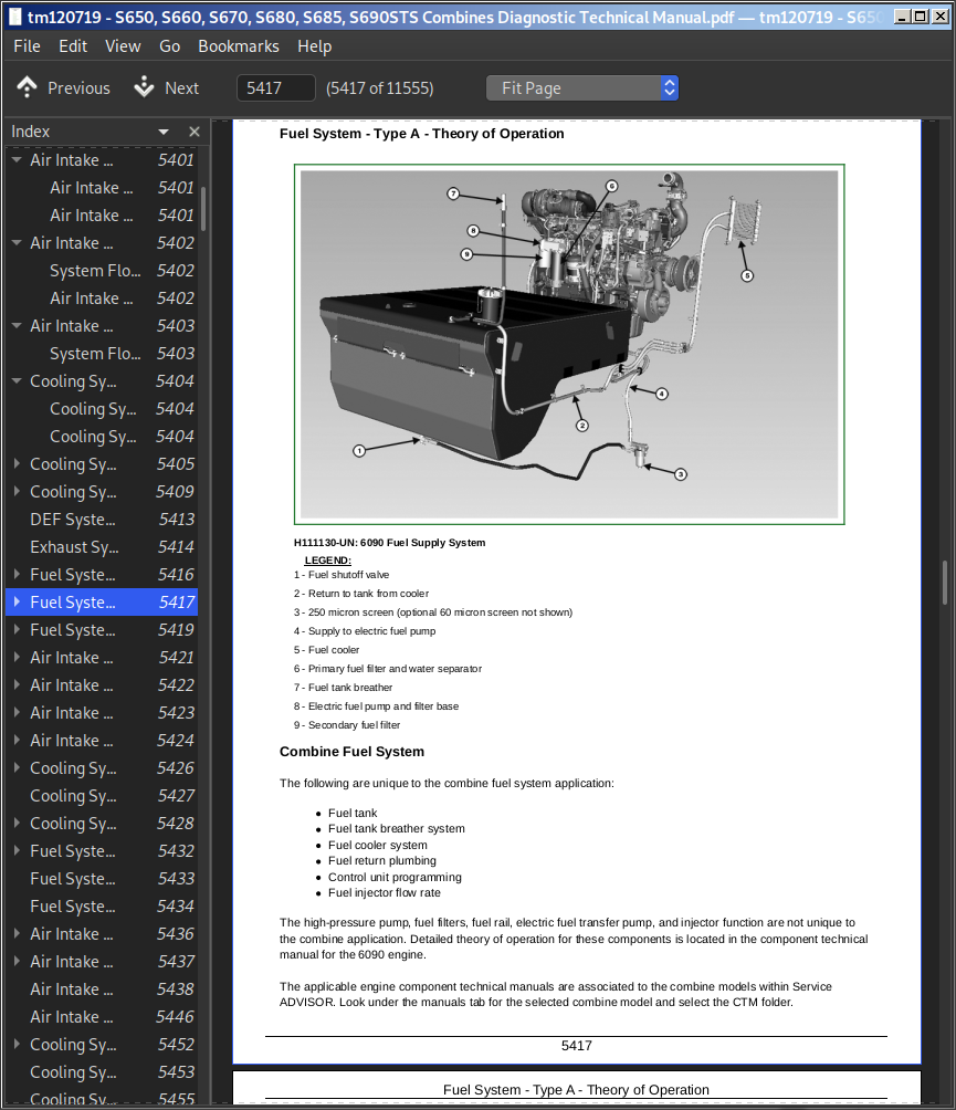
John Deere S650 S660 S670 S680 S685 S685Z S690 Combines Diagnostic & Test Service Manual TM120719 PDF - MJODTM120719.zip
A full Diagnostics & Tests guide covering John Deere S-series combines — the S650, S660, S670, S680, S685Z, and S690 (Worldwide Edition) — packed with the same technical data professionals rely on to keep, troubleshoot, and repair these machines like a dealership technician.
Inside the John Deere S650, S660, S670, S680, S685Z, and S690 combine Diagnosis & Tests manual, you'll find:
* Numbered table of contents easy to use so that you can find the information you need fast.
* Detailed sub-steps expand on repair procedure information
* Numbered instructions guide you through every repair procedure step by step.
* Troubleshooting and electrical service procedures are combined with detailed wiring diagrams for ease of use.
* Notes, cautions and warnings throughout each chapter pinpoint critical information.
* Bold figure number help you quickly match illustrations with instructions.
* Detailed illustrations, drawings and photos guide you through every procedure.
* Enlarged inset helps you identify and examine parts in detail.
TM120719 - John Deere Combines S650, S660, S670, S680, S685, S690 Technical Manual (Diagnosis & Tests).PDF
Total Pages: 11,830 pages
File Format: PDF (PC/Mac/Android/Kindle/iPhone/iPad; bookmarked, ToC, Searchable, Printable)
Language: English etc
MAIN SECTIONS
Foreword
General
Safety
Combine and Component Identification
General Specifications
Diagnostic and Testing Procedures
Diagnostic Trouble Codes
Accessing Diagnostic Codes and Addresses
ATC - Diagnostic Trouble Codes
AYM - Diagnostic Trouble Codes
CAB - Diagnostic Trouble Codes
CRU - Diagnostic Trouble Codes
CSM - Diagnostic Trouble Codes
ECU - T2, T3 and iT4 Engines - Diagnostic Trouble Codes
ECU Final Tier 4 - 9.0L Diagnostic Trouble Codes
ECU Final Tier 4 - 13.5L Diagnostic Trouble Codes
EIC - Diagnostic Trouble Codes
GLM - Diagnostic Trouble Codes
JDL - Diagnostic Trouble Codes
LC1 - Diagnostic Trouble Codes
LC2 - Diagnostic Trouble Codes
MHC - Diagnostic Trouble Codes
PDU - Diagnostic Trouble Codes
PTP - Diagnostic Trouble Codes
RC1 - Diagnostic Trouble Codes
RC2 - Diagnostic Trouble Codes
SCL - Diagnostic Trouble Codes
SFC - Diagnostic Trouble Codes
SSU - Diagnostic Trouble Codes
VTi - Diagnostic Trouble Codes
XMC - Diagnostic Trouble Codes
XSC - Diagnostic Trouble Codes
Observable Symptoms
Fuel, Air Intake, Exhaust, and Cooling Systems
Electrical System
Electrical Control Units
Drives - (S650, S660, S670)
Drives - (S680, S685, S690)
Steering and Brakes - (S650, S660, S670)
Steering and Brakes - (S680, S685, S690)
Hydraulic System - (S650, S660, S670)
Hydraulic System - (S680, S685, S690)
Main Gearcase - (S650, S660, S670)
Main Gearcase - (S680, S685, S690)
Cab/Open Operator Station
Engine System
Engine Systems
Fuel, Air Intake, Exhaust, and Cooling Systems
Theory of Operation
Schematics
Diagnostics
Air Intake and Cooling System - Components
Air Intake and Cooling System - Components - Summary of References
Air Intake and Cooling System - A Components
Air Intake and Cooling System - D Components
Air Intake and Cooling System - F Components
Air Intake and Cooling System - H Components
Air Intake and Cooling System - P Components
Air Intake and Cooling System - R Components
Air Intake and Cooling System - S Components
Air Intake and Cooling System - V Components
Electrical System
General Information
General References
Calibration Procedures
Theory of Operation - Cab/Operator’s Station
Theory of Operation - CAN Bus/Local Link Systems
Theory of Operation - Ag Management Solutions
Theory of Operation - Lighting
Theory of Operation - Engine/Fuel
Theory of Operation - Starting/Charging/Power Distribution
Theory of Operation - Header Functions
Theory of Operation - Feeder House
Theory of Operation - Threshing/Separating/Cleaning
Theory of Operation - Grain Tank/Unloading
Theory of Operation - Residue System
Theory of Operation - Transmission/Ground Drive Systems
Theory of Operation - Hydraulic Oil/Pressure
Theory of Operation - Main Gearcase
Theory of Operation - Brakes
Theory of Operation - Chassis
Schematics - Cab/Operators Station
Schematics - CAN Bus/Local Link Systems
Schematics - Ag Management Solutions
Schematics - Lighting
Schematics - Engine/Fuel
Schematics - Starting/Charging/Power Distribution
Schematics - Header Functions
Schematics - Feeder House
Schematics - Threshing/Separating/Cleaning
Schematics - Grain Tank/Unloading
Schematics - Residue System
Schematics - Transmission/Ground Drive Systems
Schematics - Hydraulic Oil/Pressure
Schematics - Main Gearcase
Schematics - Brakes
Schematics - Chassis
Diagnostics - Cab/Operator’s Station
Diagnostics - CAN Bus/Local Link Systems
Diagnostics - Ag Management Solutions
Diagnostics - Lighting
Diagnostics - Engine/Fuel
Diagnostics - Starting/Charging/Power Distribution
Diagnostics - Header Functions
Diagnostics - Feeder House
Diagnostics - Threshing/Separating/Cleaning
Diagnostics - Grain Tank/Unloading
Diagnostics - Residue System
Diagnostics - Transmission/Ground Drive Systems
Diagnostics - Hydraulic Oil/Pressure
Diagnostics - Main Gearcase
Diagnostics - Brakes
Diagnostics - Chassis
Electrical Control Units
Electrical Control Units - General Information
Accessing Diagnostic Trouble Codes and Addresses
Diagnostic Addresses by Control Unit
Theory of Operation
Schematics
Diagnostics
Electrical Connector/Components
Electrical Connector/Components - Summary of References
General Information
X100 - X149
X150 - X199
X200 - X249
X250 - X299
X300 - X349
X350 - X399
X400 - X449
X450 - X499
X500 - X549
X550 - X599
X600 - X649
X650 - X699
X700 - X749
X750 - X799
X800 - X849
X850 - X899
X900 - X949
X950 - X999
X1000 - X1049
X4000 - X4999
X5000 - X5999
X8000 - X8999
X9000 - X9999
Drives - (S650, S660, S670)
Preliminary & Operational Checks
Hydraulic Specifications
Theory of Operation
Schematics
Diagnostics
Drives - (S680, S685, S690)
Preliminary & Operational Checks
Hydraulic Specifications
Theory of Operation
Schematics
Diagnostics
Drives - Components
Drives - Components - Summary of References
Steering and Brakes - (S650, S660, S670)
Preliminary & Operational Checks
Hydraulic Specifications
Theory of Operation
Schematics
Diagnostics
Steering and Brakes - (S680, S685, S690)
Preliminary & Operational Checks
Hydraulic Specifications
Theory of Operation
Schematics
Diagnostics
Steering and Brakes - Components
Steering and Brakes - Components - Summary of References
Hydraulic System - (S650, S660, S670)
Preliminary and Operational Checks
Hydraulic Specification
Theory of Operation
Schematics
Diagnostics
Hydraulic System - (S680, S685, S690)
Preliminary & Operational Checks
Hydraulic Specifications
Theory of Operation
Schematics
Diagnostics
Hydraulic - Components
Hydraulic - Components - Summary of References
Hydraulic - A Components
Hydraulic - B Components
Hydraulic - C Components
Hydraulic - D Components
Hydraulic - F Components
Hydraulic - G Components
Hydraulic - H Components
Hydraulic - M Components
Hydraulic - O Components
Hydraulic - P Components
Hydraulic - R Components
Hydraulic - S Components
Hydraulic - V Components
Hydraulic - W Components
Hydraulic - X Components
Hydraulic - Y Components
Main Gearcase - (S650, S660, S670)
Preliminary & Operational Checks
Hydraulic Specifications
Theory of Operation
Schematics
Diagnostics
Main Gearcase (S680, S685, S690)
Preliminary & Operational Checks
Hydraulic Specifications
Theory of Operation
Schematics
Diagnostics
Main Gearcase - Components
Main Gearcase - Components - Summary of References
Cab/Open Operator’s Station
Specifications
Theory of Operation
Schematics
Diagnostics
Cab/Open Operator’s Station - Components
Cab/Open Operator Station Components
tm120719 - S650, S660, S670, S680, S685, S690STS Combines Diagnostic Technical Manual
Table of Contents
Foreword
Section 210: General
Group 05: Safety
Recognize Safety Information
Handle Fluids Safely—Avoid Fires
Prepare for Emergencies
Prevent Battery Explosions
Prevent Acid Burns
Handle Chemical Products Safely
Handle Starting Fluid Safely
Avoid High-Pressure Fluids
Park Machine Safely
Support Machine Properly
Wear Protective Clothing
Protect Against Noise
Work in Clean Area
Work In Ventilated Area
Illuminate Work Area Safely
Service Machines Safely
Construct Dealer-Made Tools Safely
Service Cooling System Safely
Service Accumulator Systems Safely
Wait Before Opening High-Pressure Fuel System
Replace Safety Signs
Use Proper Lifting Equipment
Remove Paint Before Welding or Heating
Avoid Heating Near Pressurized Fluid Lines
Service Tires Safely
Avoid Harmful Asbestos Dust
Practice Safe Maintenance
Use Proper Tools
Decommissioning — Proper Recycling and Disposal of Fluids and Components
Live With Safety
Group 10: Combine and Component Identification
Identification Numbers
Machine Identification Plate
Machine Identification Plate Location
Engine Serial Number (Tier 2/Stage II)
Engine Serial Number (Interim Tier 4/Stage III B)
Engine Serial Number (Final Tier 4/Stage IV)
Hydrostatic Drive Unit Pump (ProDrive Machines)
Hydrostatic Drive Unit Motor (ProDrive Machines)
Two-Speed Four-Wheel Drive Motor
Engine Gearcase (ProDrive Machines)
Rotor Drive Gearcase
Transmission (ProDrive Machines)
Feeder House Reverser
Multi-Speed Feeder House Gearcase (If Equipped)
Chopper (If Equipped)
Chopper Tailboard (Deluxe Residue Evacuation System)
Chopper Tailboard (Premium Residue Evacuation System)
Power Tailboard (Deluxe Residue Evacuation System)
Spreader (Deluxe Residue Evacuation System)
Hydraulic Designators
Hydraulic Circuit Symbols
Group 15: General Specifications
Operating Speeds (S650, S660 and S670)
Operating Speeds (S680, S685 and S690)