
Caterpillar 312F 313F 316F 318F Excavator Workshop Repair Service Manual PDF - MCAT312F313FOPEG.zip
This full-service repair guide for Caterpillar 312F and 313F Excavators comes complete with Electrical Wiring Diagrams, delivering every technical detail needed to service, troubleshoot, fix, and overhaul these machines the way expert technicians do.
Contained in the Caterpillar Excavators 312F/313F workshop service repair manual:
* Numbered table of contents easy to use so that you can find the information you need fast.
* Detailed sub-steps expand on repair procedure information
* Numbered instructions guide you through every repair procedure step by step.
* Troubleshooting and electrical service procedures are combined with detailed wiring diagrams for ease of use.
* Notes, cautions and warnings throughout each chapter pinpoint critical information.
* Bold figure number help you quickly match illustrations with instructions.
* Detailed illustrations, drawings and photos guide you through every procedure.
* Enlarged inset helps you identify and examine parts in detail.
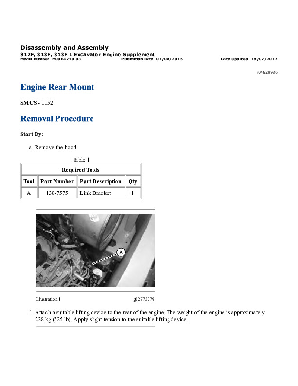
M0064710 - Disassembly and Assembly (312F; 313F; 313F L Excavator Engine Supplement).pdf
M0064712 - Disassembly and Assembly (312F; 313F; 313F L Excavator Machine Systems).pdf
M0065824 - Systems Operation (312F and 313F Excavator Machine Systems).pdf
M0065826 - Testing and Adjusting (312F and 313F Excavator Machine Systems).pdf
M0076102 - Troubleshooting (312F; 313F; 316F and 318F Excavators).pdf
M0076851 - Systems Operation (312F and 313F Excavator Machine Systems).pdf
M0105063 - Schematic (313F GC Excavator Hydraulic System - Attachment - Medium Pressure - Electric Control).pdf
UENR4516 - Disassembly and Assembly (C4.4 Engines for Caterpillar Built Machines).pdf
UENR4704 - Troubleshooting (312F GC and 313F GC Excavators).pdf
UENR5373 - Schematic (312F and 313F Excavator Hydraulic System) (426-0080-01; 504-5207-01).pdf
UENR5374 - Schematic (312F and 313F Excavator Electrical System) (KMK1-10000 PRG1-10000).pdf
UENR5375 - Schematic (312F Excavator Hydraulic System - Attachment - Combined Function - Hydraulic Control).pdf
UENR5376 - Schematic (312F Excavator Hydraulic System - Attachment - Combined Function - Hydraulic Control W_ Medium Pressure).pdf
UENR5378 - Schematic (312F Excavator Hydraulic System - Attachment - Four Way Pattern Change).pdf
UENR5379 - Schematic (312F and 313F Excavator Hydraulic System - Attachment - Combined Function - Electric Control).pdf
UENR5381 - Schematic (312F and 313F Excavator Hydraulic System - Attachment - Medium Pressure).pdf
UENR5388 - Schematic (312F and 313F Excavator Hydraulic System - Attachment - Universal Quick Coupler).pdf
UENR5643 - Specifications (312F GC and 313F GC Excavators Machine System Specifications).pdf
UENR5644 - Systems Operation (312F GC and 313F GC Excavators Machine Systems).pdf
UENR5645 - Testing and Adjusting (312F GC and 313F GC Excavators Machine Systems).pdf
UENR5646 - Systems Operation (312F GC and 313F GC Excavators Tool Control System).pdf
UENR5646 - Testing and Adjusting (312F GC and 313F GC Excavators Tool Control System).pdf
UENR5805 - Schematic (312F GC and 313F GC Excavator Electrical System) (For SN GJD1-571).pdf
UENR5806 - Schematic (312F GC and 313F GC Excavator Hydraulic System - Travel with BDRV and Travel (JS) with BDRV).pdf
UENR5808 - Schematic (312F GC and 313F GC Excavator Hydraulic System - Attachment - Blade With Medium Pressure).pdf
UENR5810 - Schematic (313F GC Excavator Hydraulic System - Attachment - Combined Function - Electric Control).pdf
UENR5812 - Schematic (312F GC and 313F GC Excavator Hydraulic System - Attachment - Load Control).pdf
UENR5814 - Schematic (313F GC Excavator Hydraulic System - Attachment - Alternate Control Pattern (Two-Way)).pdf
UENR5815 - Schematic (313F GC Excavator Hydraulic System - Attachment - Boom Lowering Control Valve).pdf
UENR5816 - Schematic (313F GC Excavator Hydraulic System - Attachment - Stick Lowering Control Valve).pdf
UENR5950 - Troubleshooting (312F; 313F; 316F and 318F Excavators).pdf
UENR6137 - Disassembly and Assembly (312F and 313F Excavators C3.4B Engine Supplement).pdf
UENR6138 - Disassembly and Assembly (312F and 313F Excavators Machine Systems).pdf
UENR6163 - Specifications (312F and 313F Excavator Machine System Specifications).pdf
UENR6168 - Schematic (312F and 313F Excavator Electrical System) (KMK10001-UP PRG10001-UP NLG10001-UP DJE10001-UP).pdf
PRODUCT DETAILS:
Total Pages: 5,103 pages
File Format: PDF (Internal Links, Bookmarked, Table of Contents, Searchable, Printable, high quality)
Language: English
TABLE OF CONTENTS
UENR4704 - Troubleshooting (312F GC and 313F GC Excavators)...4
General Information...6
Service Tools...9
Connector Locations...12
Diagnostic Capabilities...15
Diagnostic Trouble Codes...19
Determining Diagnostic Trouble Codes...25
Event Codes...31
Symptom Troubleshooting...37
Emerging Symptom Information...39
Alarm - Test...40
CAN Data Link - Test...45
Charging System - Test...54
Condition Switch (Switch to Ground) - Test...55
Electrical Connector - Inspect...60
Electrical Power Supply - Test...67
Indicator Lamp - Test...71
Relay - Test...75
Sensor Signal (Analog; Active) - Test...80
Sensor Signal (Analog; Passive) - Test...86
Sensor Signal (PWM) - Test...91
Sensor Supply - Test...101
Solenoid Valve - Test...105
Solenoid Valve (Switch Controlled) - Test...112
Switch Circuits - Test...118
Window Wiper Delay - Test...122
Wiring Harness (Open Circuit) - Test...127
Wiring Harness (Short Circuit) - Test...129
ECM Software - Install...131
ECM - Configure...133
ECM - Replace...134
Connector Contact Description...136
System Schematic...143
UENR5645 - Testing and Adjusting (312F GC and 313F GC Excavators Machine Systems)...146
General Testing and Adjusting Information...148
Visual Inspection...149
System Pressure - Release...150
Hydraulic System Air - Purge...151
Operational Checks...153
Engine Performance - Test - Engine Speed...155
Travel on Level Ground - Test - Optional Test...158
Travel on Level Ground - Test...161
Machine Drift on a Slope - Check...164
Swing Speed and Overswing on Level Ground - Check...167
Swing Speed and Swing Drift on a Slope - Check...170
Cylinder Drift - Check - Empty Bucket...174
Cylinder Drift - Check - Loaded Bucket...178
Cylinder Speed - Check...181
Accumulator (Pilot) - Test and Charge...186
Pressure Reducing Valve (Pilot Oil) - Test and Adjust...194
Power Shift Current - Check...198
Solenoid Valve (Proportional Reducing) - Calibrate - Travel Pilot Pressure Limit...200
Solenoid Valve (Proportional Reducing) - Calibrate - Power Shift Current...205
Margin Pressure - Test and Adjust...210
Relief Valve (Main) - Test and Adjust...215
Relief Valve (Line) - Test and Adjust - Blade - If Equipped...219
Relief Valve (Line) - Test and Adjust...227
Relief Valve (Blade) - Test and Adjust - If Equipped...235
Swing Motor - Test - Measurement of Case Drain Oil...243
Relief Valve (Swing) - Test and Adjust...251
Swing Bearing Movement - Measure...256
Travel Motor - Test - Measurement of Case Drain Oil...262
Relief Valve (Crossover) - Test...273
Relief Valve (Crossover) - Test and Adjust...282
Main Pump (Flow) - Test - Hydraulic Power...289
Pump Control (Output Flow) - Test...300
Pump Control (Output Flow) - Adjust...308
Specifications...310
UENR5646 - Testing and Adjusting (312F GC and 313F GC Excavators Tool Control System)...318
System Identification...319
Process for Setting Up the Work Tool...328
Work Tool Parameter - Program...346
Work Tool - Select...358
Control (Thumb Wheel) - Calibrate - If Equipped...364
Solenoid Valve (Proportional Reducing) - Calibrate - Attachment Valves...373
Combined Function - Electric Control Default Value of Work Tool Parameters...389
Combined Function - Electric Control Parameter Setting...396
Combined Function - Electric Control Parameter Adjustment...398
Combined Function - Electric Control Relief Valve (Line) - Test and Adjust...402
Combined Function - Hydraulic Control Default Value of Work Tool Parameters...411
Combined Function - Hydraulic Control Parameter Setting...418
Combined Function - Hydraulic Control Parameter Adjustment...420
Combined Function - Hydraulic Control Relief Valve (Line) - Test and Adjust...424
Medium Pressure Default Value of Work Tool Parameters - Hydraulic Control...433
Medium Pressure Default Value of Work Tool Parameters - Electric Control...440
Medium Pressure Relief Valve (Line) - Test and Adjust...446
Medium Pressure Relief Valve (Main) - Test and Adjust...456
UENR5646 - Systems Operation (312F GC and 313F GC Excavators Tool Control System)...464
General Information...465
Combined Function - Electric Control...475
Combined Function - Hydraulic Control...484
Medium Pressure Hydraulic System - Hydraulic Control...491
Medium Pressure Hydraulic System - Electric Control...496
Work Tool Parameters - Control Functions...501
Switches...505
Solenoid Valves...511
UENR5644 - Systems Operation (312F GC and 313F GC Excavators Machine Systems)...514
General Information (Boom System) ...516
General Information (Machine System)...517
Electronic Control (Machine System)...518
Machine System...546
Engine Control...550
General Information (Pilot System)...561
Electronic Control (Pilot System)...562
Pilot System...570
Accumulator (Pilot)...573
Solenoid Valve (Hydraulic Lockout)...575
Pilot Valve (Joystick)...580
Solenoid Valves - Power Shift System...583
General Information (Main Pump System)...585
Electronic Control (Main Pump System)...586
Main Hydraulic Pump...592
Pump Control (Main Hydraulic)...595
General Information (Main Control Valve)...613
Electronic Control (Main Control Valve)...614
Main Control Valve...620
General Information (Boom System)...631
Electronic Control (Boom System)...632
Boom System...640
Boom Drift Reduction Valve...644
General Information (Stick System)...649
Electronic Control (Stick System)...650
Stick System...657
General Information (Bucket System)...661
Electronic Control (Bucket System)...662
Bucket System...669
General Information (Blade System)...673
Electronic Control (Blade System)...674
Blade Hydraulic System...681
General Information (Swing System)...690
Electronic Control (Swing System)...691
Swing System...699
Swing Motor...702
Pilot Valve (Swing Parking Brake)...706
Relief Valve (Swing)...710
Oil Makeup (Swing System)...714
Relief Valve (Cushion Crossover) - Anti-Reaction Valve...720
Swing Drive...729
General Information (Travel System)...732
Electronic Control (Travel System)...733
Travel System...742
Pilot Valve (Travel)...766
Travel Motor...769
Travel Parking Brake...776
Displacement Change Valve...781
Travel Counterbalance Valve...790
Oil Makeup (Travel System)...800
Final Drive...805
Swivel...809
General Information (Return System)...813
Return Hydraulic System...814
Check Valve (Return Makeup) - Slow Return Check Valve...816
Bypass Valve (Return) - Bypass Check Valve...820
Hydraulic Tank and Filter...822
Oil Filter (Return) - Case Drain Filter...824
Hydraulic Oil Cooler...826
Shovel Crane - If Equipped...828
UENR5643 - Specifications (312F GC and 313F GC Excavators Machine System Specifications)...835
Pilot Lines (Main Pump)...838
Pump Lines...839
Pump Coupling...842
Relief Valve (Main)...844
Front Lines...845
Boom Lines...848
Boom Cylinder Lines...851
Boom Cylinder...864
Pilot Valve - Boom Load Control; RH...866
Boom - 4.65 m (15.256 ft)...868
Excavator Pins (Boom and Boom Cylinder)...870
Stick - 3.0 m (9.84 ft)...872
Stick - 2.5 m (8.20 ft)...874
Stick Lines...876
Stick Cylinder...878
Stick Cylinder Lines...880
Stick Cylinder Lines ...882
Coupler Lines...884
Bucket Cylinder Lines...885
Bucket Cylinder...886
Bucket Adjuster...888
Bucket Linkage...889
Hydraulic Tank Mounting...892
Hydraulic Tank and Filter...893
Hydraulic Oil Cooler Lines Group...897
Check Valve (Hydraulic Oil Cooler Bypass)...901
Gear Pump...902
Pilot Valve (Travel) ...903
Accumulator (Pilot)...905
Oil Filter (Return)...906
Pilot Lines...907
Pilot Lines...909
Pilot Valve (Joystick)...910
Pilot Valve (Joystick)...912
Pilot Valve (Joystick) ...914
Solenoid Valve...920
Swivel...922
Swing Motor...924
Check Valve (Slow Return)...926
Swing Drive...927
Swing Drive Mounting...929
Swing Gear and Bearing...931
Sprocket...933
Handle Control (Travel)...934
Travel Counterbalance Valve...935
Travel Motor Lines...940
Final Drive...942
Final Drive ...945
Final Drive and Motor Fastener (Mounting)...947
Travel Motor...948
Travel Motor...952
Travel Motor Guard...954
Front Idler...955
Track Adjuster...957
Track Carrier Roller...959
Track Roller (Single Flange)...961
Track...963
Fuel Tank...965
Fuel Tank and Mounting...968
Control Valve - Blade and Medium Pressure...970
Pilot Valve (Blade)...973
Blade Cylinder Lines...975
Blade Mounting...980
Counterweight Mounting...982
Auxiliary Hydraulic Lines - Coupler Lines...983
Auxiliary Hydraulic Lines...986
Grease Lines...994
Heater and Air Conditioner Mounting...996
Air Conditioner Lines...998
Refrigerant Compressor - Mounting...1000
Flood Lighting...1002
Travel Alarm...1004
Cold Weather Battery and Mounting...1005
Cab...1009
Cab - Window Guard...1011
Cab - Protection Visor...1012
Cab - Mounting...1013
Cab - Front Window Guard...1014
Cab Air Duct...1016
UENR5814 - Schematic (313F GC Excavator Hydraulic System - Attachment - Alternate Control Pattern (Two-Way))...1017
Main...1018
Features...1018
Cover Page...1019
Information...0
Component Location...1020
Tap Location...1021
Fluid Power Symbols...1022
Electrical Symbols...1023
Schematic...1024
Machine Views...0
Machine View - Right Side...1025
Main Control Valve...1026