
John Deere 1745 & 1755 Planters Frames Worldwide Diagnostic & Tests Technical Manual (TM609119) PDF - MJODTM609119.zip
Full Diagnostic & Testing Technical Manual, featuring electrical wiring schematics for the John Deere 1745 and 1755 Planter Frames (Global market), packed with every piece of service data needed to service, troubleshoot, and overhaul these machines the way expert technicians do.
The John Deere 1745 & 1755 Planter Frames (Worldwide Edition) Diagnosis & Tests workshop manual contains:
* Numbered table of contents easy to use so that you can find the information you need fast.
* Detailed sub-steps expand on repair procedure information
* Numbered instructions guide you through every repair procedure step by step.
* Troubleshooting and electrical service procedures are combined with detailed wiring diagrams for ease of use.
* Notes, cautions and warnings throughout each chapter pinpoint critical information.
* Bold figure number help you quickly match illustrations with instructions.
* Detailed illustrations, drawings and photos guide you through every procedure.
* Enlarged inset helps you identify and examine parts in detail.
tm609119 - 17451755 Diagnostic and Test Technical Manual.pdf
PRODUCT DETAILS:
Total Pages: 1,621 pages
File Format: PDF (bookmarked, ToC, Searchable, Printable, high quality)
Language: English
MAIN SECTIONS
Foreword
General Information
How to Use This Manual
Safety
Recommended Tools for Diagnostics
Basic Diagnostics
Diagnostic Information for Electrical Components
Diagnostic Information for Hydraulic Components
References for Technical Information
Specifications
Field Testing
Diagnostic Trouble Codes
PM1 Diagnostic Trouble Codes
PM2 Diagnostic Trouble Codes
Observable Symptom and System Diagnostics
Electrical
Hydraulic
Electrical
General Information
Calibration Procedure
Theory of Operation
Schematic
Diagnostic Tests and Adjustments
Electronic Control Units
General Information
Programming Electronic Control Units
SeedStar Main Control Unit - PM1 Diagnostic Addresses
SeedStar XP Meter Master Control Unit - PM2 Diagnostic Addresses
Electrical Component Information
Electrical Assemblies
Sensors
Lights
Fuses
Charging
Relays
Motors
Resistors
Switches
Interconnects and Ground Points
Electronically Actuated Mechanical Devices
Hydraulics
General Information
Calibration Procedure
Theory of Operation
Schematic
Diagnostic Tests and Adjustments
Hydraulic Component Information
Cylinder
Check Valve
Valve Block, Assembly, or Gearcase
Cooler
Motor
Orifice
Reservoir or Tank
Valve
Diagnostic Receptacle or Coupler
Solenoid Valve
Pneumatic Downforce Air Diagnostics
Calibration Procedure
Theory of Operation
Schematic
Diagnostic
Pneumatic Downforce Air Component Information
Accumulators
Sensors
Check Valves
Filters
Assembly Groups
Motors
Pumps
Reservoirs
Switches
Valves
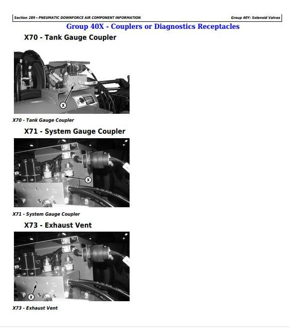
Couplers or Diagnostics Receptacles
Solenoid Valves
TABLE OF CONTENTS................1
Section 210: General Information................27
Group 05A: How to Use This Manual................27
Information is Available in Sections, Groups and Subgroups................30
Regions and Countries................31
Group 05B: Safety................27
Recognize Safety Information................33
Follow Safety Instructions................34
Understand Signal Words................35
Prevent Machine Runaway................36
Handling Batteries Safely................37
Prepare for Emergencies................39
Work in Clean Area................40
Illuminate Work Area Safely................41
Park Machine Safely................42
Service Machines Safely................43
Use Safety Lights and Devices................44
Support Machine Properly................45
Wear Protective Clothing................46
Avoid Contact with Agricultural Chemicals................47
Use Proper Tools................48
Work In Ventilated Area................49
Use Proper Lifting Equipment................50
Avoid High-Pressure Fluids................51
Service Accumulator Systems Safely................52
Handle Fluids Safely—Avoid Fires................53
Remove Paint Before Welding or Heating................54
Avoid Heating Near Pressurized Fluid Lines................55
Keep ROPS Installed Properly................56
Service Tires Safely................57
Avoid Harmful Asbestos Dust................58
Replace Safety Signs................59
Decommissioning — Proper Recycling and Disposal of Fluids and Components................60
Use Steps and Handholds Correctly................61
Clean Vehicle of Hazardous Pesticides................62
Live With Safety................63
Group 05C: Recommended Tools for Diagnostics................28
Recommended Tools................66
Group 05D: Basic Diagnostics................28
Seven Basic Steps................70
Troubleshooting Unresolved Problems................72
Group 05E: Diagnostic Information for Electrical Components................28
Electrical Designators................334
Visually Inspect Electrical System................335
Group 05F: Diagnostic Information for Hydraulic Components................1403
Hydraulic Designators................1397
Troubleshooting Tips................79
Visually Inspect Hydraulic System................1399
Group 05G: References for Technical Information................28
Metric Bolt and Screw Torque Values................84
Unified Inch Bolt and Screw Torque Values................86
Face Seal Fittings Assembly and Installation—All Pressure Applications................89
Metric Face Seal and O-Ring Stud End Fitting Torque Chart—Standard Pressures................90
Metric Face Seal and O-Ring Stud End Fitting Torque Chart—High Pressure Applications................92
SAE Face Seal and O-Ring Stud End Fitting Torque Chart—Standard Pressures................94
SAE Face Seal and O-Ring Stud End Fitting Torque Chart—High Pressure Applications................96
Four Bolt Flange Fittings Assembly and Installation—All Pressure Applications................98
SAE Four Bolt Flange Cap Screw Torque Values—Standard Pressure Applications................99
SAE Four Bolt Flange Cap Screw Torque Values—High Pressure Applications................100
External Hexagon Port Plug Torque Chart................101
Group 05H: Specifications................104
Specifications................104
Group 05I: Field Testing................109
Field Testing................109
Section 211: Diagnostic Trouble Codes................113
Group PM1: PM1 Diagnostic Trouble Codes................113
PM1 000084.09 - Wheel Speed Not Detected On CAN Bus................113
PM1 000629.14 - Planter Disabled, Cycle Power................113
PM1 001859.09 - Radar Speed Not Detected On CAN Bus................113
PM1 001859.10 - Ground Speed and Tractor Speed Conflict................113
PM1 001859.14 - Minimum Speed Not Reached At End Of Quickstart................113
PM1 003509.03 - 5 Volt Sensor Supply Voltage High................113
PM1 003509.04 - 5 Volt Sensor Supply Voltage Low................113
PM1 003510.03 - 8 Volt Sensor Supply Voltage High................113
PM1 003510.04 - 8 Volt Sensor Supply Voltage Low................113
PM1 005109.12 - Module 3 Not Responding................113
PM1 005117.01 - EPM 1 Input Voltage Low................113
PM1 005117.02 - EPM 1 Not Responding To Setup................113
PM1 005117.12 - EPM 1 Offline................113
PM1 005117.18 - EPM 1 Low Voltage On Inputs................113
PM1 005118.01 - EPM 2 Input Voltage Low................113
PM1 005118.02 - EPM 2 Not Responding To Setup................113
PM1 005118.12 - EPM 2 Offline................113
PM1 005118.18 - EPM 2 Low Voltage On Inputs................113
PM1 005119.01 - EPM 3 Input Voltage Low................113
PM1 005119.02 - EPM 3 Not Responding To Setup................113
PM1 005119.12 - EPM 3 Offline................113
PM1 005119.18 - EPM 3 Low Voltage On Inputs................113
PM1 520328.02 - Seed Detected On Row 1 While Deactivated................113
PM1 520328.12 - Row 1 Clutch Failed................113
PM1 521037.03 - Vacuum 1 Sensor Voltage High................113
PM1 521037.04 - Vacuum 1 Sensor Voltage Low................113
PM1 521037.17 - Vacuum 1 Pressure Low................113
PM1 521124.03 - Vacuum 2 Sensor Voltage High................113
PM1 521124.04 - Vacuum 2 Sensor Voltage Low................113
PM1 521124.17 - Vacuum 2 Pressure Low................113
PM1 521633.07 - VRD 1 Frequency Low................113
PM1 521633.10 - VRD 1 Frequency Abnormal................114
PM1 521726.07 - VRD 2 Frequency Low................114
PM1 521726.10 - VRD 2 Frequency Abnormal................114
PM1 522260.02 - Motion Sensor Speed and Tractor Speed Conflict................114
PM1 522260.10 - Motion Sensor Responding When No Active Tractor Speed................114
PM1 522328.02 - Seed Detected On Row 24 While Deactivated................114
PM1 522328.12 - Row 24 Clutch Failed................114
PM1 522329.02 - Seed Detected On Row 23 While Deactivated................114
PM1 522329.12 - Row 23 Clutch Failed................114
PM1 522330.02 - Seed Detected On Row 22 While Deactivated................114
PM1 522330.12 - Row 22 Clutch Failed................114
PM1 522331.02 - Seed Detected On Row 21 While Deactivated................114
PM1 522331.12 - Row 21 Clutch Failed................114
PM1 522332.02 - Seed Detected On Row 20 While Deactivated................114
PM1 522332.12 - Row 2 Clutch Failed................114
PM1 522333.02 - Seed Detected On Row 19 While Deactivated................114
PM1 522333.12 - Row 19 Clutch Failed................114
PM1 522334.02 - Seed Detected On Row 18 While Deactivated................114
PM1 522334.12 - Row 18 Clutch Failed................114
PM1 522335.02 - Seed Detected On Row 17 While Deactivated................114
PM1 522335.12 - Row 17 Clutch Failed................114
PM1 522336.02 - Seed Detected On Row 16 While Deactivated................114
PM1 522336.12 - Row 16 Clutch Failed................114
PM1 522337.02 - Seed Detected On Row 15 While Deactivated................114
PM1 522337.12 - Row 15 Clutch Failed................114
PM1 522338.02 - Seed Detected On Row 14 While Deactivated................114
PM1 522338.12 - Row 14 Clutch Failed................114
PM1 522339.02 - Seed Detected On Row 13 While Deactivated................114
PM1 522339.12 - Row 13 Clutch Failed................114
PM1 522342.02 - Seed Detected On Row 12 While Deactivated................114
PM1 522342.12 - Row 12 Clutch Failed................114
PM1 522346.02 - Seed Detected On Row 11 While Deactivated................114
PM1 522346.12 - Row 11 Clutch Failed................114
PM1 522347.02 - Seed Detected On Row 10 While Deactivated................115
PM1 522347.12 - Row 10 Clutch Failed................115
PM1 522348.02 - Seed Detected On Row 9 While Deactivated................115
PM1 522348.12 - Row 9 Clutch Failed................115
PM1 522349.02 - Seed Detected On Row 8 While Deactivated................115
PM1 522349.12 - Row 8 Clutch Failed................115
PM1 522351.02 - Seed Detected on Row 7 While Deactivated................115
PM1 522351.12 - Row 7 Clutch Failed................115
PM1 522352.02 - Seed Detected On Row 6 While Deactivated................115
PM1 522352.12 - Row 6 Clutch Failed................115
PM1 522353.02 - Seed Detected On Row 5 While Deactivated................115
PM1 522353.12 - Row 5 Clutch Failed................115
PM1 522354.02 - Seed Detected On Row 4 While Deactivated................115
PM1 522354.12 - Row 4 Clutch Failed................115
PM1 522355.02 - Seed Detected On Row 3 While Deactivated................115
PM1 522355.12 - Row 3 Clutch Failed................115
PM1 522356.02 - Seed Detected On Row 2 While Deactivated................115
PM1 522356.12 - Row 2 Clutch Failed................115
PM1 522942.09 - Planting Parameters Satisfied Before Controller Initialized................115
PM1 523111.14 - Reset System Parameters................115
PM1 523161.31 - Row 24 Seed Sensor Not Responding................115
PM1 523163.31 - Row 23 Seed Sensor Not Responding................115
PM1 523164.31 - Row 22 Seed Sensor Not Responding................115
PM1 523165.31 - Row 21 Seed Sensor Not Responding................115
PM1 523166.31 - Row 20 Seed Sensor Not Responding................115
PM1 523167.31 - Row 19 Seed Sensor Not Responding................115
PM1 523168.31 - Row 18 Seed Sensor Not Responding................115
PM1 523169.31 - Row 17 Seed Sensor Not Responding................115
PM1 523170.31 - Row 16 Seed Sensor Not Responding................115
PM1 523171.31 - Row 15 Seed Sensor Not Responding................115
PM1 523172.31 - Row 14 Seed Sensor Not Responding................115
PM1 523173.31 - Row 13 Seed Sensor Not Responding................115
PM1 523174.31 - Row 12 Seed Sensor Not Responding................115
PM1 523175.31 - Row 11 Seed Sensor Not Responding................116
PM1 523176.31 - Row 10 Seed Sensor Not Responding................116
PM1 523177.31 - Row 9 Seed Sensor Not Responding................116
PM1 523178.31 - Row 8 Seed Sensor Not Responding................116
PM1 523179.31 - Row 7 Seed Sensor Not Responding................116
PM1 523180.31 - Row 6 Seed Sensor Not Responding................116
PM1 523181.31 - Row 5 Seed Sensor Not Responding................116
PM1 523182.31 - Row 4 Seed Sensor Not Responding................116
PM1 523183.31 - Row 3 Seed Sensor Not Responding................116
PM1 523184.31 - Row 2 Seed Sensor Not Responding................116
PM1 523185.31 - Row 1 Seed Sensor Not Responding................116
PM1 523194.31 - Seed Sensor Below Normal Operating Range................116
PM1 523319.03 - ECU Power Voltage High................116
PM1 523319.04 - ECU Power Voltage Low................116
PM1 523328.11 - Height Switch Not Calibrated................116
PM1 523328.14 - Height Sensor Below Normal Operating Range................116
PM1 523436.31 - Watchdog Reset for Seed Monitor................116
PM1 523651.11 - Internal Stack Overflow................116
PM1 523652.03 - High Current Power Voltage High................116
PM1 523652.03 - High Current Power Voltage Low................116
PM1 523705.31 - Watchdog Reset For Seen Monitor And VRD................116
PM1 523773.03 - Implement CAN High Voltage High................116
PM1 523773.04 - Implement CAN High Voltage Low................116
PM1 523774.03 - Implement CAN Low Voltage High................116
PM1 523774.04 - Implement CAN Low Voltage Low................116
PM1 524055.11 - Stored NOVRAM Value Abnormal................116
Group PM2: PM2 Diagnostic Trouble Codes................116
PM2 000609.02 - Seed Monitor Not Responding................116
PM2 000609.12 - Seed Monitor Offline................116
PM2 000629.12 - Watchdog Timed Out................116
PM2 000639.12 - Implement CAN Bus Lost Message................116
PM2 000639.14 - Implement CAN Bus Excessive Errors................116
PM2 000705.13 - Node 1 Sensor Calibration Error................116
PM2 000705.19 - Node 1 Sensor Error................117
PM2 000706.13 - Node 2 Sensor Calibration Error................117
PM2 000706.19 - Node 2 Sensor Error................117
PM2 000707.13 - Node 3 Sensor Calibration Error................117
PM2 000707.19 - Node 3 Sensor Error................117
PM2 001231.12 - Left CAN Bus Lost Message................117
PM2 001231.14 - Left CAN Bus Excessive Errors................117
PM2 001235.12 - Right CAN Bus Lost Message................117
PM2 001235.14 - Right CAN Bus Excessive Errors................117
PM2 001351.14 - Compressor Motor Time Limit Exceeded................117
PM2 003509.03 - Sensor Supply Voltage High................117
PM2 003509.04 - Sensor Supply Voltage Low................117
PM2 005111.02 - Node 1 Message Missing................117