
Komatsu WA250-6 WA250PZ-6 WA250PZ-5 Wheel Loader Workshop Repair Service Manual PDF - MKMTSWA250PZ.zip
A full-service repair guide featuring Electrical Wiring Diagrams for the Komatsu WA250 and WA250PZ Wheel Loaders, supplying everything needed to service, troubleshoot, fix, and overhaul these machines the way expert technicians do.
The workshop service and repair manual for the Komatsu WA250-6 and WA250PZ-6 Wheel Loader contains:
* Numbered table of contents easy to use so that you can find the information you need fast.
* Detailed sub-steps expand on repair procedure information
* Numbered instructions guide you through every repair procedure step by step.
* Troubleshooting and electrical service procedures are combined with detailed wiring diagrams for ease of use.
* Notes, cautions and warnings throughout each chapter pinpoint critical information.
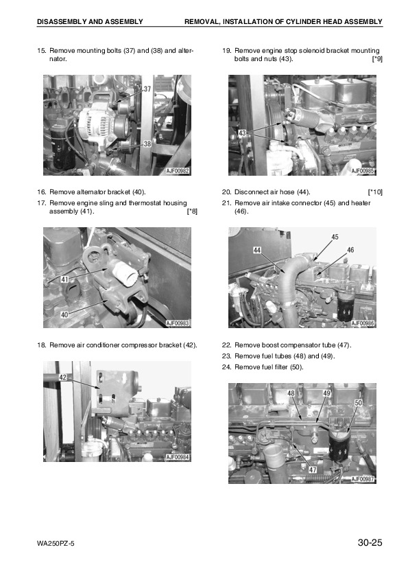
* Bold figure number help you quickly match illustrations with instructions.
* Detailed illustrations, drawings and photos guide you through every procedure.
* Enlarged inset helps you identify and examine parts in detail.
SEN03813-05 - Wheel Loader WA250-6, WA250PZ-6 Shop Manual.pdf
VEBM610101 - Wheel Loader WA250-6, WA250PZ-6 Shop Manual.pdf
VEBM945100 - Wheel Loader WA250PZ-5 Shop Manual.pdf
TEN00204-04 - Wheel Loader WA250-6 Operation & Maintenance Manual.pdf
TEN00259-04 - Wheel Loader WA250PZ-6 Operation & Maintenance Manual.pdf
TEN00408-00 - Wheel Loader WA250PZ-6 Operation & Maintenance Manual.pdf
TEN00455-01 - Wheel Loader WA250PZ-6 Operation & Maintenance Manual.pdf
VEAM945101 - Wheel Loader WA250PZ-5 Operation & Maintenance Manual.pdf
PRODUCT DETAILS:
Total Pages: 2,112 pages
File Format: PDF (Internal Links, Bookmarked, Table of Contents, Searchable, Printable, high quality)
Language: English
TABLE OF CONTENTS
SEN03813-05 - Wheel Loader WA250-6, WA250PZ-6 Shop Manual....2
Cover....2
00 Index and foreword....0
100 Index....4
Composition of shop manual....5
Table of contents....7
200 Foreword and general information....18
Safety notice....19
How to read the shop manual....24
Explanation of terms for maintenance standard....26
Handling of electric equipment and hydraulic component....28
Handling of connectors newly used for engines....37
How to read electric wire code....40
Precautions when carrying out operation....43
Method of disassembling and connecting push-pull type coupler....46
Standard tightening torque table....49
Conversion table....53
01 Specification....0
100 Specification and technical data....60
Specification dimension drawing....62
Specifications....63
Weight table....67
Table of fuel, coolant and lubricants....69
10 Structure, function and maintenance standard....0
100 Engine and cooling system....72
Engine mount and transfer mount....73
Damper....74
Cooling system....75
Cooling system hydraulic piping diagram....76
Cooling fan motor....78
200 Power train....88
Power train....90
Power train system diagram....91
Drive shaft....93
HST hydraulic piping diagram....94
HST pump....95
HST motor....103
Transfer....109
Clutch solenoid valve....120
Axle....121
Differential....123
Torque proportioning differential....128
Limited slip differential....131
Final drive....135
300 Steering system....142
Steering piping diagram....144
Steering column....145
Priority valve....146
Orbit-roll valve....149
2-way restrictor valve....157
Cushion valve....158
Steering cylinder....159
Emergency steering piping diagram....161
Emergency steering valve....162
Steering relief valve....165
400 Brake system....168
Brake piping diagram....170
Charge valve....171
Brake valve....175
Inching valve....179
Accumulator (for brake)....180
Slack adjuster....181
Brake....183
Parking brake control....188
Parking brake....189
500 Undercarriage and frame....192
Axle mount and center hinge pin....193
Tires....198
600 Hydraulic system....200
Work equipment hydraulic piping diagram....201
Work equipment control lever linkage....205
Hydraulic tank....209
4-gear pump....211
Work equipment control valve....213
PPC valve....238
Lock valve....253
Accumulator (for PPC circuit)....254
Bypass valve....255
Quick coupler solenoid valve....258
ECSS valve....259
Accumulator (for ECSS)....261
700 Work equipment....264
Work equipment linkage....265
Bucket....269
Bucket positioner and boom kick-out....273
Work equipment cylinder....286
800 Cab and its attachments....290
Cab....292
Air conditioner....293
910 Electrical system, Part 1....306
Machine monitor system....307
Machine monitor....311
920 Electrical system, Part 2....334
Electrical system (HST controller system)....335
HST controller....351
ECSS system....353
KOMTRAX system....355
Engine starting circuit....357
Engine stopping circuit....359
Preheating circuit....360
Engine output derating function....361
Automatic warm-up function....361
Parking brake circuit....362
Coupler plunger control system....365
Multi-function knob....366
Max. traction switch....367
Sensor....368
20 Standard value table....0
100 Standard service value table....376
Standard service value table....377
Standard service value table for chassis....378
30 Testing and adjusting....0
110 Testing and adjusting, Part 1....386
Tools for testing, adjusting, and troubleshooting....389
Sketches of special tools....394
Measuring engine speed....395
Measuring exhaust gas color....397
Adjusting valve clearance....399
Measuring compression pressure....401
Measuring blow-by pressure....404
Measuring engine oil pressure....405
Measuring intake air (boost) pressure....406
Handling fuel system equipment....408
Releasing residual pressure in fuel system....408
Measuring fuel pressure....409
Measuring fuel return rate and leakage....411
Bleeding air from fuel circuit....415
Testing leakage in fuel system....416
Handling reduced cylinder mode operation....417
Handling no-injection cranking operation....417
Handling controller voltage circuit....418
Check of muffler and muffler stack for looseness and damage....418
Check of muffler function....419
Check of installed condition of cylinder head and manifolds....419
Check of engine piping for damage and looseness....420
Testing and adjusting air conditioner compressor belt tension....420
Replacing alternator belt....421
120 Testing and adjusting, Part 2....424
Checking operating force of accelerator pedal....426
Checking directional lever....427
Testing and adjusting HST oil pressure....428
Testing clutch control pressure....432
Testing and adjusting steering wheel....433
Testing and adjusting steering oil pressure....435
Bleeding air from steering circuit....437
Testing hydraulic fan....438
Measuring brake pedal....440
Testing and adjusting brake pedal linkage....441
Measuring brake performance....442
Testing and adjusting accumulator charge pressure....443
Testing wheel brake oil pressure....445
Testing wear of brake disc....448
Bleeding air from wheel brake circuit....449
Releasing residual pressure in brake accumulator circuit....450
Testing parking brake performance....451
Testing and adjusting parking brake control cable....452
Measuring and adjusting work equipment control lever....453
Testing and adjusting work equipment hydraulic pressure....454
Testing work equipment PPC oil pressure....455
Bleeding air from hydraulic circuit....457
Releasing remaining pressure in hydraulic circuit....458
Testing and adjusting bucket positioner....459
Testing and adjusting of boom kick-out switch....460
Checking proximity switch operation pilot lamp....461
Procedure for testing diodes....462
Preparation work for troubleshooting for electric system....464
Starting KOMTRAX terminal operations....468
Indicator lamps of KOMTRAX terminal....472
130 Testing and adjusting, Part 3....476
Adjusting machine monitor....477
Adjusting replaced, reassembled or added sensor, controller, etc. with machine monitor....478
Special functions of machine monitor (EMMS)....480
Pm clinic inspection chart....534
40 Troubleshooting....0
100 Failure code table and fuse locations....538
Failure codes table....539
Fuse locations....545
200 General information on troubleshooting....550
Points to remember when troubleshooting....551
Sequence of events in troubleshooting....552
Testing before troubleshooting....553
Classification and procedures of troubleshooting....554
Information contained in troubleshooting table....557
Connection table for connector pin numbers....559
T- branch box and T- branch adapter table....595
310 Troubleshooting by failure code (Display of code), Part 1....600
Failure code [2G40GZ] Brake: Oil pressure reduction....601
Failure code [6091NX] HST filter: Clogging....603
Failure code [989FN1] Travel speed: Overrun alarm....605
Failure code [AB00L6] Alternator R system: Hot short....607
Failure code [AB00MA] Alternator R system: Ground fault/Disconnection charge/Low charge voltage....609
Failure code [B@BAZG] Engine: Oil pressure reduction....611
Failure code [B@BCNS] Engine: Overheat....612
Failure code [B@BCZK] Engine: Low coolant level....613
Failure code [B@C6NS] Front brake: High oil temperature....615
Failure code [B@CRNS] HST: High oil temperature....616
320 Troubleshooting by failure code (Display of code), Part 2....618
Failure code [CA111] Abnormality in engine controller....620
Failure code [CA115] Engine Ne or Bkup speed sensor error....621
Failure code [CA122] Charge pressure sensor high error....623
Failure code [CA123] Charge pressure sensor low error....625
Failure code [CA131] Throttle sensor high error....627
Failure code [CA132] Throttle sensor low error....629
Failure code [CA144] Coolant sensor high error....631
Failure code [CA145] Coolant sensor low error....633
Failure code [CA153] Charge temperature sensor high error....635
Failure code [CA154] Charge temperature sensor low error....637
Failure code [CA155] Derating of speed by abnormally high charge temperature....639
Failure code [CA187] Sensor power supply 2 low error....641
Failure code [CA221] Atmospheric pressure sensor high error....643
Failure code [CA222] Atmospheric sensor low error....645
Failure code [CA227] Sensor power supply 2 high error....647
Failure code [CA234] Engine overspeed....648
Failure code [CA238] Ne speed sensor power supply error....649
Failure code [CA271] IMV (IMA) Short circuit....650
Failure code [CA272] IMV (IMA) Disconnection....651
Failure code [CA322] Injector #1 open/short error....653
Failure code [CA323] Injector #5 open/short error....655
Failure code [CA324] Injector #3 open/short error....657
Failure code [CA325] Injector #6 open/short error....659
Failure code [CA331] Injector #2 open/short error....661
Failure code [CA332] Injector #4 open/short error....663
Failure code [CA342] Calibration code inconsistency....665
Failure code [CA351] Injectors drive circuit error....667
Failure code [CA352] Sensor power supply 1 low error....669
Failure code [CA386] Sensor power supply 1 high error....671
330 Troubleshooting by failure code (Display of code), Part 3....674
Failure code [CA428] Abnormally high level in water sensor....677
Failure code [CA429] Abnormally low level in water sensor....679
Failure code [CA431] Idle validation switch error....681
Failure code [CA432] Idle validation action error....685
Failure code [CA435] Engine oil pressure switch error....689
Failure code [CA441] Battery voltage low error....690
Failure code [CA442] Battery voltage high error....693
Failure code [CA449] Common rail pressure high error 2....695
Failure code [CA451] Common rail pressure sensor high error....697
Failure code [CA452] Common rail pressure sensor low error....699
Failure code [CA488] Derating of torque by abnormally high charge temperature....701
Failure code [CA553] Common rail pressure high error 1....702
Failure code [CA559] Supply pump pressure very low error....703
Failure code [CA689] Engine Ne speed sensor error....705
Failure code [CA731] Engine Bkup speed sensor phase error....707
Failure code [CA757] All continuous data lost error....708
Failure code [CA778] Engine Bkup speed sensor error....711
Failure code [CA1633] KOMNET datalink timeout error....713
Failure code [CA2185] Throttle sensor supply voltage high error....717
Failure code [CA2186] Throttle sensor power supply low error....719
Failure code [CA2249] Supply pump pressure very low error 2....721
Failure code [CA2311] Abnormality in IMV (IMA) solenoid....723
Failure code [CA2555] Intake heater relay disconnection error....725
Failure code [CA2556] Intake heater relay short circuit error....727
340 Troubleshooting by failure code (Display of code), Part 4....730
Failure code [D160KY] Backup alarm/lamp relay 1 circuit: Hot short....731
Failure code [D192KY] ECSS solenoid relay: Hot short....733
Failure code [D1B0KA] HST safety relay: Disconnection....735
Failure code [D1B0KB] HST safety relay: Ground fault....737
Failure code [D1B0KY] HST safety relay: Hot short....739
Failure code [D5ZHL6] IGN C system: Ground fault/Disconnection....741
Failure code [DAF3KK] UNSW power supply: Ground fault/Disconnection....743
Failure code [DAFRKR] Machine monitor CAN-NET Signal: Disconnection....745
Failure code [DAJ0KK] HST controller power supply: Low voltage....749
Failure code [DAJ0KT] HST controller memory (EEPROM): Abnormality....751
Failure code [DAJ1L4] HST controller main power line: Disconnection/Ground fault....753
Failure code [DAJ1L6] HST controller main power line: Hot short....755
Failure code [DAJ2KK] Controller solenoid power supply: Low voltage....757
Failure code [DAJ2L3] HST controller load power supply holding line: Hot short in wiring harness....759
Failure code [DAJ2L4] HST controller load power supply holding line: Disconnection/Ground fault....761
Failure code [DAJ5KX] Sensor 5V power supply: Out of output range....763
Failure code [DAJ9KQ] HST controller model selection: Disagreement of model selection signals....765
Failure code [DAJRKR] HST controller CAN-NET signal: Disconnection....766
Failure code [DAJRMA] HST controller: Disagreement in option selection....772
350 Troubleshooting by failure code (Display of code), Part 5....774
Failure code [DB2RKR] Engine controller CAN-NET: Disconnection in signal line....776
Failure code [DD1NL4] Fan automatic reverse switch signal: Abnormality....781
Failure code [DD1NLD] Fan reverse switch signal: Abnormality....783
Failure code [DDB6KA] Parking brake switch A: Disconnection/Hot short....785
Failure code [DDB6KB] Parking brake switch B: Ground fault....787