
John Deere 5080G 5090G 5090GH 5080GV 5090GV 5100GV 5080GF 5090GF 5100GF Tractor Diagnostic & Tests Service Manual TM402419 PDF - MJODTM402419.zip
John Deere Tractors 5090G, 5090GV, 5090GF, 5100GV, 5100GF, 5090GH, 5080GV, 5080GF, 5080G Diagnosis & Tests Service Manual (TM402419)
TM402419 — Technical Manual (Diagnosis & Test) for the John Deere 5080G–5090G tractors, along with the 5090GH, 5080GV–5100GV and 5080GF–5100GF models, supplied in PDF format.
Complete Diagnostic & Tests service manual with Electrical Wiring Diagrams for John Deere Tractor 5080G, 5090G, 5090GH, 5080GV, 5090GV, 5100GV, 5080GF, 5090GF, 5100GF (Worldwide Models, 2WD/MFWD), with all the shop information to maintain, diagnostic, repair, service like professional mechanics.
John Deere Tractors 5080G, 5090G, 5090GH, 5080GV, 5090GV, 5100GV, 5080GF, 5090GF workshop Operation & Tests manual includes:
* Numbered table of contents easy to use so that you can find the information you need fast.
* Detailed sub-steps expand on repair procedure information
* Numbered instructions guide you through every repair procedure step by step.
* Troubleshooting and electrical service procedures are combined with detailed wiring diagrams for ease of use.
* Notes, cautions and warnings throughout each chapter pinpoint critical information.
* Bold figure number help you quickly match illustrations with instructions.
* Detailed illustrations, drawings and photos guide you through every procedure.
* Enlarged inset helps you identify and examine parts in detail.
Total Pages: 1,653 pages
File Format: PDF (bookmarked, ToC, Searchable, Printable, high quality)
Language: English
MAIN SECTIONS
Foreword
General Information
Safety Measures
General References
Diagnostic Trouble Codes
Transmission Control Unit (EHM III)
Electronic Hitch Sensing
Observable Symptoms
Fuel and Air Intake System
Electrical System
Electronics
Power Train
Steering and Brakes
Hydraulic System
Front-Wheel Drive
Air-Conditioning System
Engine
Operational Check-Out
Tests and Adjustments
Fuel, Air Intake and Cooling Systems
Tests and Adjustments
Theory of Operation
Electrical System
SE01-Starting Motor and Charging System
SE02-Instrument Panel
SE03-Horn
SE04-Lighting System
SE05-Work Lights-Cab
SE06-Radio, Dome and Spot Light
SE07-Fan and Air-Conditioning System
SE08-Windshield Wiper and Washer System
SE09-Rear Window Wiper and Washer System
SE10-Beacon Light
SE11-Power Outlet
SE12-Electronic Hitch Sensing (EHS II)
SE13-Hazard Warning and Turn Signal Lights
SE14-PTO Warning and Speed System
SE15-Front-Wheel Drive and Park Brake
SE16-Differential Lock
SE17-Brake System
SE18-Electro-Hydraulic Hi-Lo
SE19-Controller Area Network (CAN)
SE20 - Transmission Control Unit
Component Information-Connectors
Component Information-Wiring Harnesses
Component Information-Electrical Parts
Component Information-Ground Connection
Wiring Diagrams up to Serial Number 920065
Wiring Diagrams from Serial Number 920066
Electronic Control Units
Operation and General Information on Diagnostics
Information on How to Reprogram Control Units
TCU - Transmission Control Unit
EHS II - Electronic Hitch Sensing
Power Train
Component Location
Theory of Operation
Diagnosis, Tests and Adjustments
24/12-Speed Transmission
Operational Checks
Tests and Adjustments
Theory of Operation
Drive Systems
Component Location
Tests and Adjustments
Front-Wheel Drive
Differential
Final Drives
Rear PTO
Steering and Brake Systems
Component Location
Theory of Operation
Diagnosis, Tests and Adjustments
Hydraulic System
Component Location
Theory of Operation
Diagnosis
Tests
Adjustments
Hydraulic System Schematics
Miscellaneous
Operational Checks
Air-Conditioning System
Component Location
Theory of Operation
Diagnosis, Tests and Adjustments
Special Tools
Special Tools (Dealer-Fabricated)
Special Tools (Available as Spare Parts)
tm402419 - 5080G-5090G, 5090GH,5080GV-5100GV and 5080GF-5100GF Tractors Diagnostics
Table of Contents
Foreword
Section 210: General Information
Group 05: Safety Measures
Recognize Safety Information
Understand Signal Words
“Important” - Information
”Note” Information
Follow Safety Instructions
Handle Fluids Safely—Avoid Fires
Prevent Battery Explosions
Prepare for Emergencies
Prevent Acid Burns
Service Cooling System Safely
Avoid High-Pressure Fluids
Park Machine Safely
Support Machine Properly
Wear Protective Clothing
Work in Clean Area
Service Machines Safely
Work In Ventilated Area
Illuminate Work Area Safely
Replace Safety Signs
Use Proper Lifting Equipment
Keep ROPS Installed Properly
Service Tires Safely
Avoid Harmful Asbestos Dust
Avoid Heating Near Pressurized Fluid Lines
Remove Paint Before Welding or Heating
Use Proper Tools
Dispose of Waste Properly
Use Safety Lights and Devices
Practice Safe Maintenance
Service Front-Wheel Drive Tractor Safely
Live With Safety
Group 10: General References
General Information - General References, Summary of References
General Information - Electrical System, Approach to Tabular Diagnostic Procedures
General Information - Electrical System, Troubleshooting Unsolved Problems
General Information - Electrical System, Worksheet for Circuit/Harness Test
General Information - Electrical System, Visual Check
General Information - Electrical System, Electrical Circuit Malfunctions
Section 211: Diagnostic Trouble Codes
Group TCU: Transmission Control Unit (EHM III)
TCU 000126.02 - Oil Filter Restricted Sensor Fault
TCU 000126.31 - Transmission Oil Filter Restricted
TCU 000127.02 - Transmission Oil Pressure Detected with Engine Off
TCU 000127.07 - Transmission Oil Pressure Detected with Shut-Off Solenoid Valve Deactivated
TCU 000127.31 - Transmission Oil Pressure too Low
TCU 000177.00 - Transmission Oil Temperature too High
TCU 000177.01 - Transmission Oil Temperature too Low
TCU 000177.05 - Transmission Oil Temperature Sensor, Signal Voltage too High
TCU 000177.06 - Transmission Oil Temperature Sensor, Signal Voltage too Low
TCU 000522.31 - INFORMATION FOR OPERATOR: Clutch Pedal not Completely Released
TCU 000598.02 - Clutch Pedal Potentiometer and Clutch Pedal Switch, Signals Mismatch
TCU 000629.12 - Control Unit Internal Fault
TCU 000629.14 - Control Unit Internal Fault
TCU 000629.31 - Control Unit Internal Fault
TCU 000630.02 - Calibration Parameters Out of Range
TCU 000630.31 - Calibration Parameters Saving Fault
TCU 000639.31 - CAN BUS, High Error Rate
TCU 000788.06 - Forward High Clutch or Reverse Clutch, Current too High
TCU 000976.31 - PTO Switch Fault
TCU 001565.00 - INFORMATION FOR OPERATOR: Move Reverse Drive Lever to Neutral
TCU 003509.00 - 5-Volt Supply Voltage too Low
TCU 003509.01 - 5-Volt Supply Voltage too High
TCU 003593.06 - Current too High at All Outputs to Solenoid Valve
TCU 003596.06 - PTO Mode Indicator Lights, Current too High
TCU 003599.06 - PTO Shut-Off Solenoid Valve, Current too High
TCU 521215.00 - PTO Pressure Detected with PTO Shut-Off Solenoid Valve Not Activated
TCU 521215.15 - PTO Pressure Detected with PTO Solenoid Valve Not Activated
TCU 521215.16 - PTO Pressure Detected with PTO Switched Off
TCU 521215.18 - PTO Pressure Not Detected with PTO Switched On
TCU 521216.31 - INFORMATION FOR OPERATOR: Stop Tractor, System Check in Process
TCU 521221.00 - Forward Low Clutch, Unexpected Slip
TCU 521221.06 - Forward Low Clutch, Current too High
TCU 521222.00 - Forward High Clutch, Unexpected Slip
TCU 521230.02 - Reverse Drive Lever Switch Fault, Neutral and Reverse Signals Received Simultaneously
TCU 521230.07 - Reverse Drive Lever Switch Fault, Neutral and Forward Signals Received Simultaneously
TCU 521230.14 - Reverse Drive Lever Switch Fault, Forward and Reverse Signals Received Simultaneously
TCU 521230.31 - Reverse Drive Lever Switch Fault, Neutral, Forward and Reverse Signals Received Simultaneously
TCU 521233.00 - Forward High Clutch Solenoid Valve, Feedback Current Present with Solenoid Valve Not Activated
TCU 521233.01 - Forward High Clutch Solenoid Valve, Feedback Current Not Present with Solenoid Valve Activated
TCU 521233.31 - Forward High Clutch Solenoid Valve, Measured and Reference Current Mismatch
TCU 521234.00 - Forward Low Clutch Solenoid Valve, Feedback Current Present with Solenoid Valve Not Activated
TCU 521234.01 - Forward Low Clutch Solenoid Valve, Feedback Current Not Present with Solenoid Valve Activated
TCU 521234.31 - Forward Low Clutch Solenoid Valve, Measured and Reference Current Mismatch
TCU 521235.00 - Reverse Clutch Solenoid Valve, Feedback Current Present with Solenoid Valve Not Activated
TCU 521235.01 - Reverse Clutch Solenoid Valve, Feedback Current Not Present with Solenoid Valve Activated
TCU 521235.31 - Reverse Clutch Solenoid Valve, Measured and Reference Current Mismatch
TCU 521236.06 - Shut-Off Solenoid Valve, Overcurrent or Shorted to Ground
TCU 521236.31 - Shut-Off Solenoid Valve, Feedback Current too High
TCU 521237.00 - Forward High Clutch, Pressure too High
TCU 521237.01 - Forward High Clutch, Pressure too Low
TCU 521237.03 - Forward High Clutch Pressure Sensor, Signal Voltage too High
TCU 521237.04 - Forward High Clutch Pressure Sensor, Signal Voltage too Low
TCU 521237.14 - Forward High Clutch, Pressure Difference too High
TCU 521237.31 - Forward High Clutch Solenoid Valve, Fault
TCU 521238.00 - Forward Low Clutch, Pressure too High
TCU 521238.01 - Forward Low Clutch, Pressure too Low
TCU 521238.03 - Forward Low Clutch Pressure Sensor, Signal Voltage too High
TCU 521238.04 - Forward Low Clutch Pressure Sensor, Signal Voltage too Low
TCU 521238.14 - Forward Low Clutch, Pressure Difference too High
TCU 521238.31 - Forward Low Clutch Solenoid Valve, Fault
TCU 521239.00 - Reverse Clutch, Pressure too High
TCU 521239.01 - Reverse Clutch, Pressure too Low
TCU 521239.03 - Reverse Clutch Pressure Sensor, Signal Voltage too High
TCU 521239.04 - Reverse clutch pressure sensor signal too low
TCU 521239.14 - Reverse Clutch, Pressure Difference too High
TCU 521239.31 - Reverse Clutch Solenoid Valve, Fault
TCU 522383.00 - Reverse Clutch, Unexpected Slip
TCU 522402.02 - Transmission Speed Sensor, Signal Faulty
TCU 522402.08 - Transmission Speed Sensor, Fault
TCU 523666.00 - Control Unit, Supply Voltage too High
TCU 523666.01 - Control Unit, Supply Voltage too Low
TCU 523735.14 - Driving Clutch Solenoid Valves Activated without a signal from the Reverse Drive Lever
TCU 523735.31 - Driving Clutch Solenoid Valves Activated with Reverse Drive Lever in Neutral or Clutch Pedal Completely Depressed
TCU 524173.00 - Clutch Pedal Potentiometer, Value too High
TCU 524173.01 - Clutch Pedal Potentiometer, Value too Low
TCU 524173.03 - Clutch Pedal Potentiometer, Output Voltage too High
TCU 524173.04 - Clutch Pedal Potentiometer, Output Voltage too Low
Group EHS II: Electronic Hitch Sensing
Electronic Hitch Sensing (Summary of References)
Diagnosis (EHS II)
EHS01 - Position Sensor Failure
EHS02 - Draft Sensor Failure
EHS04 - EPROM Reading Failure
EHS08 - Power Supply Less Than 10 Volts
EHS16 - Power Supply Greater Than 16 Volts
EHS32 - Lowering Solenoid Valve Failure
EHS64 - Raising Solenoid Valve Failure
Section 212: Observable Symptoms
Group 30: Fuel and Air Intake System
Fuel and Air Intake Problems
Group 40: Electrical System
Electrical System (Summary of References)
Starting System Diagnostics
Charging System Diagnostics
Lighting System Diagnostics
Group 45: Electronics
CAN BUS check
Group 50: Power Train
Drive System Diagnostics
Group 60: Steering and Brakes
Problems with the Brakes
Problems with the Steering System
Problems with the Trailer Brakes
Group 70: Hydraulic System
Problems with the Hydraulic System
Group 80: Front-Wheel Drive
Problems with the Front-Wheel Drive
Group 90: Air-Conditioning System
Problems with the Air-Conditioning System
Section 220: Engine
Group 10: Operational Check-Out
Operational Check-Out (Summary of References)
Safety
Preliminary Engine Tests
Group 15: Tests and Adjustments
Tests and Adjustments (Summary of References)
Dynamometer Test
Section 230: Fuel, Air Intake and Cooling Systems
Group 15: Tests and Adjustments
Summary of References - Tests and Adjustments
General Information
Explanation of Checks
Safety
Special Tools
Specifications
Test Air Intake System
Test the Low-Pressure Switch in Air Intake System
Check the Cooling System for Leaks
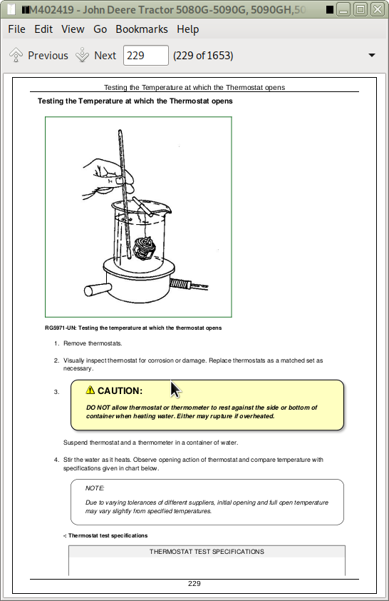
Testing the Temperature at which the Thermostat opens
Checking the Viscous Clutch of the Fan
Check the Fuel Transfer Pump
Hand Throttle Lever and Accelerator Pedal Adjustment
Group 20: Theory of Operation
Summary of References - Theory of Operation
Fuel System - Description (Standard Tractors)
Fuel System - Description (F and V Tractors)
Air Intake System - Theory of Operation
Engine Cooling System Operation
Cooling System Radiator — Description
Viscous Clutch of Fan — Theory of Operation
Automatic Drive Belt Tensioner — Theory of Operation
Cold Weather Starting Aid — Theory of Operation
Section 240: Electrical System
Group S01: SE01—Starting Motor and Charging System
SE01—Starting Motor and Charging System (Summary of References)
Diagnostic Schematic, SE01—Starting Motor and Charging Circuit
Diagnostic Schematic, SE01—Intake Air Heater Circuit
Group S02: SE02—Instrument Panel
SE02 - Instrument Panel (Summary of References)
Diagnostic Schematic, SE02 - Instrument Panel