
John Deere 6405 6605 Tractor Diagnostic & Test Service Manual TM4576 PDF - MJODTM4576.zip
Full service and repair reference featuring electrical schematics for the John Deere 6405 and 6605 Tractors, available in 2WD or MFWD configurations — everything a trained technician needs to service, troubleshoot, and overhaul these machines.
Inside the Diagnostics & Tests technical manual for the John Deere 6405 and 6605 tractors, you'll find:
* Numbered table of contents easy to use so that you can find the information you need fast.
* Detailed sub-steps expand on repair procedure information
* Numbered instructions guide you through every repair procedure step by step.
* Troubleshooting and electrical service procedures are combined with detailed wiring diagrams for ease of use.
* Notes, cautions and warnings throughout each chapter pinpoint critical information.
* Bold figure number help you quickly match illustrations with instructions.
* Detailed illustrations, drawings and photos guide you through every procedure.
* Enlarged inset helps you identify and examine parts in detail.
tm4576 - 6405 and 6605 tractors Technical Manual - Diagnosis and Tests.pdf
tm4576 - 6405 and 6605 tractors Technical Manual - Diagnosis and Tests.epub
Total Pages: 1,304 pages
File Format: PDF/EPUB/MOBI/AZW (PC/Mac/Android/Kindle/iPhone/iPad; bookmarked, ToC, Searchable, Printable)
Language: English
MAIN SECTIONS
Foreword
Safety
Safety
Service Code Diagnosis
HCU Code Diagnostics
Observable Symptom
Electrical
Power Take-Off
Hitch
Engine
Tests
Fuel, Air Intake and Cooling Systems
System Diagnosis
Tests and Adjustments
Fuel System
Air Intake System
Cooling System
Cold Weather Starting Aids
Electrical System
General
System Diagrams (Operator's Station)
System Diagrams (Tractors with Cab)
Sub-System Diagnostics (Operator's Station)
Sub-System Diagnostics (Tractors with Cab)
Component Testing
Electronic Control Units
Operation and General Information on Diagnostics
HCU References
SYNCROPLUS Transmission
Operational Checkout
Troubleshooting
Tests and Adjustments
SyncroPlus Transmission Operation
Perma Clutch II
Gear Transmission
Creeper Transmission
Range Transmission
POWRREVERSER Transmission
Operational Checkout
Troubleshooting
Test and Adjustments
Power Reverser Operation
Power Reverser Module
Gear Transmission
Drive Systems
Operational Checks
System Diagnosis
Tests
Front-Wheel Drive Clutch
Differential
Final Drives
Rear PTO Options
Front PTO
Steering and Brakes
Operational Checks
System Diagnosis
System Tests
Hydrostatic Steering
Hydraulic Brakes
Hydraulic System
Operational Checkout
Hydraulic System Troubleshooting
Tests and Adjustments
HYDRAVANTAGE Hydraulic System and Components
Hydraulic Pump
Valves, Oil Cooler and Filter
Rockshaft
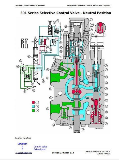
Selective Control Valves and Couplers
Independent Control Valve (ICV)
Operator's Cab
Operational Checkout
Air Conditioner Troubleshooting
Ventilation and Heater Troubleshooting
Air Conditioner Operation
Ventilation and Heating Operation
Special Tools (Dealer-Fabricated)
tm4576 - 6405 and 6605 tractors
Table of Contents
Foreword
Section 210: Safety
Group 05: Safety
Recognize Safety Information
“Important” - Information
“Note” - Information
Prevent Machine Runaway
Handle Fluids Safely-Avoid Fires
Prevent Battery Explosions
Prepare for Emergencies
Prevent Acid Burns
Avoid High-Pressure Fluids
Service Cooling System Safely
Remove Paint Before Welding or Heating
Avoid Heating Near Pressurized Fluid Lines
Work In Ventilated Area
Wear Protective Clothing
Practice Safe Maintenance
Park Machine Safely
Use Proper Lifting Equipment
Construct Dealer-Made Tools Safely
Support Machine Properly
Work in Clean Area
Illuminate Work Area Safely
Service Machines Safely
Use Proper Tools
Service Tires Safely
Service Front-Wheel Drive Tractor Safely
Safety Information - Air Brake System
Avoid Eye Contact with Radar
Keep ROPS Installed Properly
Replace Safety Signs
Dispose of Waste Properly
Live With Safety
Section 211: Service Code Diagnosis
Group HCU: HCU Code Diagnostics
HCU 022-System Voltage not in Specification
HCU 027-Calibration not Successful
HCU 028-Calibration Memory Failure
HCU 029-Calibration Memory Failure
HCU 030-Insignificant Fault that has no Effect on Tractor Operation
HCU 041-Stepper Motor Circuit Open
HCU 042-Stepper Motor Circuit Open
HCU 043-Stepper Motor Circuit Shorted
HCU 044-Stepper Motor Circuit Shorted
HCU 045-Potentiometers and Position Sensor Supply Voltage Out of Range
HCU 046-Draft Sensor Supply voltage Out of Range
HCU 049-Quick Raise/Lower Rocker Switch Circuit
HCU 050-Stepper Motor Deadband out of range
HCU 051-Left Draft Sensor Signal Circuit
HCU 052-Right Draft Sensor Signal Circuit
HCU 053-Load/Depth Control Potentiometer Circuit
HCU 054-Hitch Control Lever Potentiometer Circuit
HCU 055-Hitch Position Sensor Circuit
HCU 056-Raise Limit Control Potentiometer
HCU 057-Rate-of-Drop Control Potentiometer Circuit
HCU 058-Remote Control Switch Circuit
HCU 239-Circuit fault during Calibration
HCU 241-Hitch Position Sensor Circuit fault during Calibration
HCU 242-Hitch Position Sensor Circuit fault during Calibration
HCU 250-Right Draft Sensor Circuit out of specification during calibration
HCU 251-Right Draft Sensor Circuit out of specification during calibration
HCU 252-Right Draft Sensor Circuit out of specification during calibration
HCU 253-Left Draft Sensor Circuit out of specification during calibration
HCU 254-Left Draft Sensor Circuit out of specification during calibration
HCU 255-Left Draft Sensor Circuit out of specification during calibration
Section 212: Observable Symptom
Group 40: Electrical
HCU Controller not Displayed
Group 56: Power Take-Off
Rear PTO Will Not Run
Rear PTO Will Not Stop Turning
PTO Slips Under Load
Group 70: Hitch
Hitch Does Not Work
Hitch Remote Control Does Not Work
Section 220: Engine
Group 10: Tests
Safety Measures
Preliminary Engine Tests
Dynamometer Test
Section 230: Fuel, Air Intake and Cooling Systems
Group 10: System Diagnosis
Fuel System
Cooling System
Group 15: Tests and Adjustments
General Information
Explanation of Checks
Safety Measures
Special Tools
Specifications
Testing the Air Intake System
Testing the Low-Pressure Switch in Air Intake System
Checking the Cooling System for Leaks
Checking Expansion Tank Cap
Test Thermostat Opening Temperature
Checking the Viscous Fan Drive
Checking the Fuel Transfer Pump
General Information on Diagnostics
Adjust Hand Throttle Lever and Accelerator Pedal
Group 20A: Fuel System
General Information
Description
Fuel Transfer Pump - Theory of Operation
Fuel Filter - Theory of Operation
Group 20B: Air Intake System
Air Cleaner - Theory of Operation
Group 20C: Cooling System
General Information
Description of Radiator
Automatic Drive Belt Tensioner - Theory of Operation
Viscous Fan Drive - Theory of Operation
Group 20D: Cold Weather Starting Aids
General Information
Electrical Starting Aid - Theory of Operation
Fuel Preheater - Theory of Operation
Coolant Heater - Theory of Operation
Section 240: Electrical System
Group 05: General
Electrical Circuit Malfunctions
Group 10: System Diagrams (Operator's Station)
Fuses
Component Designations on Functional Schematics and Wiring Harnesses
Section Designations on Functional Schematics
Wiring Harness Identification
Functional Schematic - Complete Tractor
W3 - Wiring Harness for 4-Cylinder Engine (AL117076)
W3 - Wiring Harness for 6-Cylinder Engine (AL117226)
Wiring Harness for Electrical Starting Aid (W27; AL119472)
Front Corner Worklight Wiring Harness (W14; AL81307)
Platform Wiring Harness (W4; AL117225) up to Serial Number 249394
Platform Wiring Harness (W4; AL119281) from Serial Number 249395
7-Pin Socket Wiring Harness (W28; AL150291)
3-Pin Socket Wiring Harness (W30; AL114896)
Front Part of Transmission Wiring Harness (W32; AL115344)
Rear Part of Transmission Wiring Harness (W33; AL116810)
W40 - Wiring Harness - Back-Up Alarm (AL117624)
W41 - Wiring Harness - Back-Up Alarm -Switch for SynchroPlus Transmission (AL114955)
Group 10A: System Diagrams (Tractors with Cab)
Fuses
Part Designations in Functional Schematic and Wiring Harnesses
Section Designations on Functional Schematics
Wiring Harness Identification
Functional Schematic (Complete Tractor)
W3 - Wiring Harness for 4-Cylinder Engine (AL150218)
W3 - Wiring Harness for 6-Cylinder Engine (AL150219)
Wiring Harness for Electrical Starting Aid (W27; AL119472)
Front PTO Wiring Harness (W39; AL110126)
W4 - Cab Wiring Harness (AL153711)
W30 - 3-Pin Socket Wiring Harness (AL114896)
W11 - Cab Roof Wiring Harness (AL153454)
W8 - Air Conditioner and Fan Wiring Harness (AL110589)
W13 - Transmission Wiring Harness (AL153957)
W40 - Wiring Harness - Back-Up Alarm (AL117624)
W41 - Wiring Harness - Back-Up Alarm -Switch for SynchroPlus Transmission (AL114955)
Group 15: Sub-System Diagnostics (Operator's Station)
Special or Essential Tools
SE1-Starting Motor and Charging Circuit, Functional and Diagnostic Schematic
SE2-Basic Informator, Functional and Diagnostic Schematic
SE3-Horn, Functional and Diagnostic Schematic
SE5-Rear PTO, Functional and Diagnostic Schematic
SE6-Lights, Functional and Diagnostic Schematic
SE7-Work Lights, Functional and Diagnostic Schematic
SE8-Front Loader Plug, Functional and Diagnostic Schematic
SE14-3-Pin- and 7-Pin Receptacle, Functional and Diagnostic Schematic
SE15-Electronic Hitch Control, Functional and Diagnostic Schematic
SE16A-Hazard Flashers and Turn Signals, Functional and Diagnostic Schematic (up to Serial No. 249394)
SE16A-Hazard Flashers and Turn Signals, Functional and Diagnostic Schematic (from Serial No. 249395)
SE16B-Front Wheel Drive, Functional and Diagnostic Schematic
SE16C-Differential Lock, Functional and Diagnostic Schematic
SE25-Back-Up Alarm, Functional and Diagnostic Schematic
Group 15A: Sub-System Diagnostics (Tractors with Cab)
Special or Essential Tools
SE1-Starter Motor and Charging Circuit
SE2-Instrument Panel
SE3-Horn
SE4-Operator's Seat
SE5A-Front PTO
SE5B-Rear PTO
SE6-Lighting Circuits
SE7-Work Light
SE9A-3- and 7-Pin Power Outlet Sockets
SE9B-Radio, Dome and Console Lights
SE10-Fan and Air Conditioner
SE11-Windshield Wiper and Washer
S13-Beacon
SE15-Electronic Hitch Control Unit (HCU)
SE16A-Hazard Warning Flasher and Turn Signal Lights
SE16C-Brake System
SE16D-Differential Lock
SE16E-Front Wheel Drive
SE25-Back-Up Alarm, Functional and Diagnostic Schematic
Group 25: Component Testing
Special or Essential Tools
Specifications
SE1-Starting Motor and Charging Circuit
SE2-Instrument Unit and Lighting
SE3-Horn
SE4-Operator Seat
SE5A-Front PTO
SE5 or SE5B-Rear PTO
SE6-Lighting Circuits
SE7-Work Light
SE9B-Radio, Dome and Shift Console Lights
SE10-Fan and Air Conditioner
SE11-Windshield Wiper and Washer