
John Deere 625D 630D 635D 640D Draper Platform Repair Technical Manual TM103919 PDF - MJODTM103919.zip
An in-depth service guide featuring complete wiring schematics for the John Deere 625D, 630D, 635D and 640D Draper Platform, packed with every shop detail needed to upkeep, troubleshoot, fix and overhaul these machines just as trained technicians would.
The John Deere 625D, 630D, 635D and 640D Draper Platform workshop service repair manual contains:
* Numbered table of contents easy to use so that you can find the information you need fast.
* Detailed sub-steps expand on repair procedure information
* Numbered instructions guide you through every repair procedure step by step.
* Troubleshooting and electrical service procedures are combined with detailed wiring diagrams for ease of use.
* Notes, cautions and warnings throughout each chapter pinpoint critical information.
* Bold figure number help you quickly match illustrations with instructions.
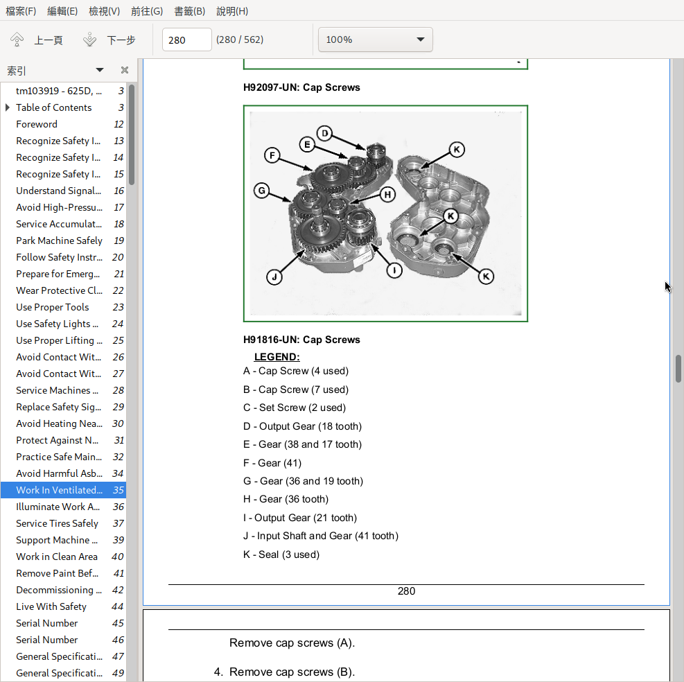
* Detailed illustrations, drawings and photos guide you through every procedure.
* Enlarged inset helps you identify and examine parts in detail.
tm103919 - 625D, 630D, 635D and 640D Draper Platforms Repair Technical Manual.pdf
PRODUCT DETAILS:
Total Pages: 562 pages
File Format: PDF (bookmarked, ToC, Searchable, Printable, high quality)
Language: English
MAIN SECTIONS
Foreword
General
Safety
Identification
Specifications
Lubrication
Cutterbar
Platform Cutterbar
Feed Drum, Reel And Top Auger
Feed Drum Repair
Reel Repair
Top Auger Repair
Electrical
Components
Harness and Connector Repair
Drives
Gear Cases
Drivelines
Knife Drive
Draper Belt
Draper Belt Assembly
Deck Shift
Hydraulics
Cylinders
Motors and Pump
Valves
Multi-Coupler
Accumulator
Frame
Transport
tm103919 - 625D, 630D, 635D and 640D Draper Platforms Repair
Table of Contents
Foreword
Section 10: General
Group 05: Safety
Recognize Safety Information
Understand Signal Words
Avoid High-Pressure Fluids
Service Accumulator Systems Safely
Park Machine Safely
Follow Safety Instructions
Prepare for Emergencies
Wear Protective Clothing
Use Proper Tools
Use Safety Lights and Devices
Use Proper Lifting Equipment
Avoid Contact With Moving Parts
Avoid Contact With Cutterbar
Service Machines Safely
Replace Safety Signs
Avoid Heating Near Pressurized Fluid Lines
Protect Against Noise
Practice Safe Maintenance
Avoid Harmful Asbestos Dust
Work In Ventilated Area
Illuminate Work Area Safely
Service Tires Safely
Support Machine Properly
Work in Clean Area
Remove Paint Before Welding or Heating
Decommissioning — Proper Recycling and Disposal of Fluids and Components
Live With Safety
Group 10: Identification
Serial Number
Group 15: Specifications
General Specifications
Dimensions
Hydraulic Specifications
Platform Weights
Metric Bolt and Screw Torque Values
Unified Inch Bolt and Screw Torque Values
Face Seal Fittings Assembly and Installation—All Pressure Applications
Metric Face Seal and O-Ring Stud End Fitting Torque Chart—Standard Pressures
SAE Face Seal and O-Ring Stud End Fitting Torque Chart—Standard Pressures
Group 20: Lubrication
Draper Main Gear Case
Grease
Section 20: Cutterbar
Group 05: Platform Cutterbar
Other Material
Specifications
Remove Knife Head Bearing
Repair Knife Head Bearing
Install Knife Head Bearing
Remove Knife Head
Install Knife Head
Remove Knife Assembly
Install Knife Assembly
Knife Hold-Down Clearance
Replacing Knife Sections
Adjust Knife System
Cutterbar Knife Timing
Section 30: Feed Drum, Reel And Top Auger
Group 05: Feed Drum Repair
Specifications
Remove and Install Feed Drum
Disassemble and Assemble Feed Drum Fingers, Cranks And Shafts
Adjust Feed Drum Finger Timing
Group 10: Reel Repair
Service Equipment and Tools
Specifications
Remove and Install Single Reel
Remove and Install Split Reel
Disassemble and Assemble Reel
Disassemble and Assemble Split Reel Coupler
Remove and Install Reel Roller Bearing
Remove and Install Left-Hand Reel Support Slide Assembly
Remove and Install Right-Hand Reel Support Slide Assembly
Disassemble and Assemble Reel Support Slide Assembly
Adjust Pickup Finger Pitch
Group 15: Top Auger Repair
Specifications
Remove and Install Top Augers
Remove and Install Top Auger Bearings
Section 40: Electrical
Group 05: Components
Specifications
Remove and Install Hazard Warning Light and Bracket Assembly
Remove and Install Transport Lights
Light Bulb Replacement
Remove and Install Reel Speed Sensor
Remove and Install Draper Belt Speed Sensor
Remove and Install Control Block Pressure Sensor
Group 10: Harness and Connector Repair
Essential or Recommended Tools
Other Material
Wiring Harness Routing—Right-Hand Side
Wiring Harness Routing—Left-Hand Side
Use Electrical Insulating Compound
Using High-Pressure Washers
Connector Identification
Electrical Connector / Wiring Harness Handling and Repair
Installation of Repair Wire Assembly (RWA)
Repair Procedure R-A
Repair Procedure R-B
Repair Procedure R-C
Repair Procedure R-E
Repair Procedure R-G
Section 50: Drives
Group 05: Gear Cases
Essential or Recommended Tools
Other Material
Specifications
Remove and Install Main Drive Gear Case
Disassemble and Assemble Main Drive Gear Case
Remove and Install Center Feed Gear Case
Disassemble and Assemble Center Feed Gear Case
Remove and Install 90° Gear Case (Left-Hand Side)
Remove and Install 90° Gear Case (Right-Hand Side)
Disassemble and Assemble 90° Gear Case
Remove and Install 90° Gear Case With Belt Drive Pump
Disassemble and Assemble 90° Gear Case With Belt Drive Pump
Group 10: Drivelines
Other Material
Remove and Install Backshaft
Remove and Install 90° Gear Case Drive Shaft
Remove and Install Feed Drum Slip Clutch
Group 15: Knife Drive
Essential Or Recommended Tools
Other Material
Specifications
Remove and Install Knife Drive Belt
Knife Drive Gear Case—Exploded View
Remove and Install Knife Drive Gear Case
Disassemble and Assemble Knife Drive Gear Case
Section 60: Draper Belt
Group 05: Draper Belt Assembly
Specifications
Remove and Install Side Belt Assembly
Remove and Install Side Belt Drive Roller
Remove and Install Side Belt Idler Roller
Remove and Install Center Draper Belt Drive Roller
Remove and Install Center Belt Idler Roller
Group 10: Deck Shift
Specifications
Remove and Install Deck Shift Drive Sprocket
Remove and Install Manual Deck Shift Drive Bearings
Remove and Install Deck Shift Chain
Deck Shift Chain Tensioner Exploded View
Section 70: Hydraulics
Group 05: Cylinders
Specifications
Remove and Install Reel Lift Cylinders—Single Reel
Remove and Install Reel Lift Cylinder—Split Reel
Remove and Install Reel Lift Supply Cylinders—Split Reel
Remove and Install Reel Fore/Aft Cylinders
Remove and Install Frame Float Cylinders
Remove and Install Wheel Cylinders
Remove and Install Cutterbar Tilt Cylinder
Disassemble and Assemble 150 Series Hydraulic Cylinders
Rephase Reel Fore/Aft Cylinders
Rephase Reel Lift Cylinders
Bleeding Reel Lift Cylinder System
Group 10: Motors and Pump
Specifications
Remove and Install Reel Drive Motor
Remove and Install Left-Hand and Right-Hand Draper Drive Motors—Style A
Remove and Install Left-Hand and Right-Hand Draper Drive Motors—Style B
Remove and Install Belt Drive Pump
Remove and Install Top Auger Drive Motor
Remove and Install Deck Shift Motor
Group 15: Valves
Specifications
Remove and Install Header Control Block
Disassemble and Assemble Header Control Block
Remove and Install Pump Control Block
Disassemble and Assemble Pump Control Block
Remove and Install Reel Phasing Valve Block
Top Auger Flow Control Valve Exploded View
Deck Shift Valve Block Disassemble and Assemble—Left-Hand Side
Deck Shift Valve Block Disassemble and Assemble—Right-Hand Side
Remove and Install Check Valve Block
Disassemble and Assemble Check Valve Block
Group 20: Multi-Coupler
Specifications
Remove and Install Multi-Coupler Hydraulic Connectors
Disassemble and Assemble Multi-Coupler Cartridge
Group 25: Accumulator
Specifications
Relieve Hydraulic System Pressure
Accumulator (General Information)
Remove and Install Accumulator—Style A
Remove and Install Accumulator—Style B
Checking Accumulator Pressure—Style A
Checking Accumulator Pressure—Style B
Section 80: Frame
Group 05: Transport
Specifications
Other Material
Gauge Wheel—Exploded View
Remove and Install Front Transport and Gauge Wheel Assembly
Front Transport Wheel Assembly—Exploded View
Left Rear Transport Wheel Assembly—Exploded View
Right Rear Transport Wheel Assembly—Exploded View
Remove and Install Rear Transport Wheel Assembly
John Deere Hay and Forage Draper Platforms Models 625D, 630D, 635D, 640D Repair Service Technical Manual (TM103919)