
John Deere 1705 1715 1725 1735 1755 1765 1775 1785 1795 Planter Frame Workshop Repair Manual PDF (TM131319) - MJODTM131319.zip
A full-service technical repair guide covering the John Deere 1705, 1715, 1725, 1735, 1755, 1765, 1775, 1785, and 1795 Planter Frame, packed with every shop detail needed to service, fix, and rebuild the equipment just like an expert technician.
This John Deere 1705, 1715, 1725, 1735, 1755, 1765, 1775, 1785, 1795 Planter Frame repair workshop manual contains the following:
* Numbered table of contents easy to use so that you can find the information you need fast.
* Detailed sub-steps expand on repair procedure information
* Numbered instructions guide you through every repair procedure step by step.
* Troubleshooting and electrical service procedures are combined with detailed wiring diagrams for ease of use.
* Notes, cautions and warnings throughout each chapter pinpoint critical information.
* Bold figure number help you quickly match illustrations with instructions.
* Detailed illustrations, drawings and photos guide you through every procedure.
* Enlarged inset helps you identify and examine parts in detail.
tm131319 - 1705 Series Planter Frame Repair Technical Manual Technical Manual.pdf
PRODUCT DETAILS:
Total Pages: 1,149 pages
File Format: PDF (bookmarked, ToC, Searchable, Printable, high quality)
Language: English
MAIN SECTIONS
Foreword
General Information
Safety
Lubricants
General Information
Vacuum System
Vacuum System
Central Commodity System
Seed Tanks and Manifolds
Seed Delivery Hose
Central Commodity System Fan
Electrical
Connector Repair
Control Units
Relays, Sensors, and Switches
Lighting Repair
Batteries
Generator
Drives
Specifications
Seed Drive Transmissions
Half Width Disconnect
Drill Shafts
Variable Rate Drive
Charging System Drive
Hitch and Frame
Repair and Welding
Hitch Pads
Wheel Module Repair
Row Markers
Loading Platform and Hitch
Rockshafts
Lift Assist
Hydraulics
General Information
Motors
Cylinders
Valve Block
Valves
Miscellaneous
Fertilizer and Pesticide Systems
Liquid Fertilizer System
Variable Rate Fertilizer
Pesticide System
Pneumatic Down Force
General Information
Pneumatic Down Force
Active Pneumatic Down Force
Miscellaneous
Polyethylene Tank Repair
Dealer Fabricated Tools
TABLE OF CONTENTS................1
Section 10: General Information................18
Group 05: Safety................18
Recognize Safety Information................21
Understand Signal Words................22
Handle Fluids Safely—Avoid Fires................23
Prevent Battery Explosions................24
Handling Batteries Safely................25
Prevent Acid Burns................27
Prepare for Emergencies................29
Avoid Harmful Asbestos Dust................30
Practice Safe Maintenance................31
Avoid High-Pressure Fluids................33
Park Machine Safely................34
Support Machine Properly................35
Wear Protective Clothing................36
Handle Agricultural Chemicals Safely................37
Work in Clean Area................39
Service Machines Safely................40
Work In Ventilated Area................41
Illuminate Work Area Safely................42
Replace Safety Signs................43
Use Proper Lifting Equipment................44
Remove Paint Before Welding or Heating................45
Avoid Heating Near Pressurized Fluid Lines................46
Service Accumulator Systems Safely................877
Service Tires Safely................48
Use Proper Tools................49
Construct Dealer-Made Tools Safely................50
Decommissioning — Proper Recycling and Disposal of Fluids and Components................51
Live With Safety................52
Servicing Electronic Control Units................53
Welding Near Electronic Control Units................54
Precautions for Welding................572
Keep Electronic Control Unit Connectors Clean................57
Group 10: Lubricants................19
Multipurpose Grease................59
Multipurpose Extreme Pressure (EP) Grease................60
Gear Oil................61
Alternative and Synthetic Lubricants................62
Lubricant Storage................63
Group 15: General Information................19
Unauthorized Modifications................65
Specifications—1705, 1705 Twin Row, 1715, and 1735................66
Dimensions—1705, 1705 Twin Row, 1715, and 1735................69
Specifications—1725, 1725NT, 1725C, 1725 CCS, and 1725 CCS Twin Row................70
Dimensions—1725, 1725NT, 1725 CCS, and 1725 CCS Twin Row................74
Specifications—1755 and 1785................75
Dimensions—1755 and 1785................78
Specifications—1765 and 1765NT................79
Dimensions—1765 and 1765NT................81
Specifications—1775NT 12 Row................82
Dimensions—1775NT 12 Row................85
Specifications—1775NT 16 Row................87
Dimensions—1775NT 16 Row................90
Specifications—1775NT 24 Row................92
Dimensions—1775NT 24 Row................95
Specifications—1795................98
Dimensions—1795................103
Sealants and Adhesives Cross-Reference Chart................105
Metric Bolt and Screw Torque Values................107
Unified Inch Bolt and Screw Torque Values................109
Face Seal Fittings Assembly and Installation—All Pressure Applications................111
Metric Face Seal Fitting Torque Chart—Standard Pressure Applications................112
SAE Face Seal Fitting Torque Chart—Standard Pressure Applications................114
External Hexagon Port Plug Torque Chart................116
Section 20: Vacuum System................118
Group 05: Vacuum System................118
Specifications................1104
Adjust Vacuum Gauge................121
Vacuum Manifold Blower System................122
Vacuum Manifold System Exploded View................123
Vacuum Manifold System Exploded View—With Dust Suppression System................124
Inspect and Adjust Vacuum Coupler Bell—1795................125
Clean Vacuum Manifold System................127
Repair Vacuum Monitoring Assembly —Two Vacuum Gauges................128
Repair Vacuum Monitoring Assembly with SeedStar™................130
Remove and Install Vacuum Blower Assembly—Style A................132
Disassemble and Assemble Vacuum Blower Assembly—Style A................134
Remove and Install Vacuum Blower Assembly—Style B................139
Disassemble and Assemble Vacuum Blower Assembly—Style B................140
Section 30: Central Commodity System................144
Group 05: Seed Tanks and Manifolds................144
Other Material................1103
Specifications................1104
Remove and Install Seed Tanks................148
Remove and Install Refuge Plus Third Tank................152
Tank Repair................906
Seal Central Commodity System Tanks To Prevent Water Leakage................156
Remove and Install Seed Agitator Motor Assembly................159
Remove and Install Seed Delivery Manifold Seal................162
Remove and Install Seed Delivery Manifold Nozzle................171
Repair Central Commodity System Seed Tank Manifold................177
Remove and Install Seed Tank Lid Ring and Seal................179
Group 10: Seed Delivery Hose................144
Other Material................1103
Remove and Install Seed Delivery Hose................187
Repair Seed Delivery Hose................188
Group 15: Central Commodity System Fan................144
Specifications................1104
Remove and Install Central Commodity System Blower Fan................192
Repair Central Commodity System Blower Fan Assembly................196
Section 40: Electrical................200
Group 05: Connector Repair................200
Essential or Recommended Tools................1133
Other Material................1103
Installation of Repair Wire Assembly (RWA)................213
Use Electrical Insulating Compound................222
Using High-Pressure Washers................223
Connector Information................224
Repair Procedure R-A................225
Repair Procedure R-B................230
Repair Procedure R-C................235
Repair Procedure R-D................240
Repair Procedure R-E................243
Repair Procedure R-F................247
Repair Procedure R-G................251
Repair Procedure R-I................254
Repair Procedure R-J................257
Repair Procedure R-K................262
Repair Procedure R-M................265
Repair Procedure R-N................269
Repair Procedure R-T................273
Repair Procedure R-AA................274
Repair Procedure R-AE................275
Replace Fold-Unfold Circuit Diode................279
Remove and Install Frame Control Harness................281
Group 10: Control Units................200
Remove and Install Electronic Power Generation (EPG) Control Unit................293
Remove and Install Modular Telematics Gateway (MTG) Control Unit................294
Remove and Install Planter Main Controller (PMC)................295
Remove and Install Wireless Data Server (WDS) Control Unit................296
Remove and Install ExactRate™ Main Control Unit................297
Remove and Install ExactRate™ Flow Detection Module................298
Update Control Units Using Service Advisor™................299
Programming Control Units................302
Group 15: Relays, Sensors, and Switches................201
Other Material................1103
Specifications................1104
Repair Planter Control Box................308
Replace Marker Switch................315
Replace Marker Winglet Switch................316
Adjust Marker Winglet Switch................317
Replace Fold Control Switch—Style A................319
Replace Fold Control Switch—Style B................320
Replace Central Commodity System Push Button Shut-Off Switch................321
Replace Central Commodity System Cleanout Switch................322
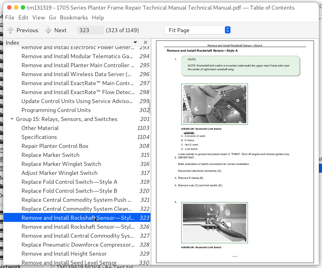
Remove and Install Rockshaft Sensor—Style A................323
Remove and Install Rockshaft Sensor—Style B................326
Remove and Install Central Commodity System Loading Platform Light Switch................327
Replace Pneumatic Downforce Compressor Pressure Switch................328
Remove and Install Height Sensor................329
Remove and Install Seed Level Sensor................330
Remove and Install Wheel Speed Sensor (Style A)................332
Remove and Install Wheel Speed Sensor (Style B)................334
Remove and Install Hopper Level Sensor................335
Remove and Install Liquid Fertilizer Sensor................336
Remove and Install Pneumatic Downforce Pressure Sensor................337
Remove and Install Active Pneumatic Downforce Pressure Sensor................338
Remove and Install Active Pneumatic Downforce Pressure Switch................339
Remove and Install Variable Rate Fertilizer Pump Speed Sensor................340
Remove Variable Rate Fertilizer Cam Position Sensor................341
Install Variable Rate Fertilizer Cam Position Sensor................342
Remove and Install Variable Rate Drive Motor Speed Sensor................344
Remove and Install Lift Assist Steering Position Sensor................345
Remove and Install Generator Speed Sensor—Style A................346
Remove and Install Generator Speed Sensor—Style B................347
Remove and Install Generator Current Sensor................348
Remove and Install Generator Motor Pressure Sensor................349
Remove and Install ExactEmerge Fuse Box................350
Remove and Install Battery Fuse................351
Remove and Install Temperature Sensor—Tractor Power Generation................354
Remove and Install Frame Weight Distribution Switch................355
Remove and Install ExactRate™ System Pressure Sensor................356
Remove and Install ExactRate™ Nozzle Pressure Sensor................357
Remove and Install ExactRate™ Pump Speed Sensor................358
Remove and Install ExactRate™ Flowmeter................359
Remove and Install ExactRate™ Keypad................360
Relay Identification................361
Group 20: Lighting Repair................202
Repair Red Warning Lamp................366
Repair Amber Warning Lamp................368
Repair Red Warning Lamp—CCS................370
Repair Amber Warning Lamp—CCS................371
Red and Amber Warning Lamps—1705 Twin Row................372
Red and Amber Warning Lamps—1725 CCS................373
Group 25: Batteries................202
Essential or Recommended Tools................1133
Specifications................1104
Prevent Damage to Electrical Systems................377
Remove and Install Control Unit Battery................378
Remove and Install ExactEmerge Batteries................380
Charging Batteries................385
Connecting Battery Cables................387
Group 30: Generator................202
Other Material................1103
Specifications................1104
Remove and Install Generator................392
Remove and Install Generator—Tractor Power Generation................394
Remove and Install Generator Splined Coupler—Tractor Power Generation................397
Group 35: Miscellaneous................202
Remove and Install ExactRate™ DC to DC Inverter................399
Calibrate ExactRate™ Nozzle Pressure Sensor................400
Calibrate ExactRate™ Flowmeter................406
Calibrate ExactRate™ System Pressure Sensor................409
Calibrate ExactRate™ Solution Pump................413
Section 50: Drives................417
Group 05: Specifications................1104
Drive Chain Specifications................1104
Shear Pin Specifications................1104
Sprocket Specifications................1104
Spur Gear Specifications................1104
Group 10: Seed Drive Transmissions................417
Specifications................1104
Seed Drive Transmission Exploded View—1705, 1715, 1725 and 1755................437
Seed Drive Transmission Exploded View—1705 Twin Row................439
Seed Drive Transmission Exploded View—1705 Twin Row with Variable Rate Drive................554
Seed Drive Transmission Exploded View—1735................443
Seed Drive Transmission Exploded View—1765................446
Seed Drive Transmission Exploded View—1775NT................448
Seed Drive Transmission Exploded View—1775NT 24 Row................452
Seed Drive Transmission Exploded View—1785................454
Seed Drive Transmission Exploded View—1795................456
Remove and Install Seed Drive Transmission—1775NT................458
Remove and Install Seed Drive Transmission—1775NT 24 Row................464
Remove and Install Seed Drive Transmission—1795................466
Adjust Seed Drive Transmission—1775NT................467
Adjust Contact Link—1775NT 24 Row................468
Adjust Contact Link—1795................470
Check and Adjust Transmission Spur Gear Backlash................471
Disassemble and Assemble Tire Contact Seed Transmission................473
Disassemble and Assemble Ground Driven Seed Transmission................496
Group 15: Half Width Disconnect................417