
Bobcat 763 763 High Flow 773 773 High Flow 773 Turbo G Series Loader Workshop Repair Service Manual PDF - MBOB763773.zip
Full service manuals featuring electrical schematics for the Bobcat 763, 763 High Flow, 773, 773 High Flow, and 773 Turbo (G Series) Loaders, offering the technical detail needed to maintain, troubleshoot, fix, and service these machines the way professional technicians do.
The Bobcat 763, 763 High Flow, 773, 773 High Flow, and 773 Turbo (G Series) Loader workshop service repair manual contains:
* Numbered table of contents easy to use so that you can find the information you need fast.
* Detailed sub-steps expand on repair procedure information
* Numbered instructions guide you through every repair procedure step by step.
* Troubleshooting and electrical service procedures are combined with detailed wiring diagrams for ease of use.
* Notes, cautions and warnings throughout each chapter pinpoint critical information.
* Bold figure number help you quickly match illustrations with instructions.
* Detailed illustrations, drawings and photos guide you through every procedure.
* Enlarged inset helps you identify and examine parts in detail.
MAIN SECTIONS
CONTENTS
FOREWORD
SAFETY INSTRUCTIONS
SERIAL NUMBER LOCATION
DELIVERY REPORT
BOBCAT LOADER IDENTIFICATION
SAFETY AND MAINTENANCE
HYDRAULIC SYSTEM
HYDROSTATIC SYSTEM
DRIVE SYSTEM
MAIN FRAME
ELECTRICAL SYSTEM & ANALYSIS
ENGINE SERVICE
HEATER
SPECIFICATIONS
Total Pages: 7,680 pages
File Format: PDF (bookmarked, Searchable, Printable, high quality)
Language: English
6900091 (5-11) - 763, 763 High Flow Service Manual.pdf
6900091 (6-12) - 763, 763 High Flow Service Manual.pdf
6900091 (6-97) - 763, 763 High Flow Service Manual.pdf
6900092 (6-12) - 773 Service Manual.pdf
6900092 (6-97) - 773 Service Manual.pdf
6900371 (8-00) - 763, 763 High Flow Operation & Maintenance Manual.pdf
6900372 (5-01) - 773 Operation & Maintenance Manual.pdf
6900788 (9-00) - 763, 763 High Flow Operation & Maintenance Manual.pdf
6900789 (9-00) - 773 Operation & Maintenance Manual.pdf
6900834 (3-06) - 773, 773 High Flow, 773 Turbo (G Series) Service Manual.pdf
6900834 (6-12) - 773, 773 High Flow, 773 Turbo (G Series) Service Manual.pdf
6900842 (12-06) - 773, 773 High Flow Operation & Maintenance Manual.pdf
6900939 (5-05) - 773 G-Series Parts Manual.pdf
6900971 (7-03) - 763, 763 High Flow Operation & Maintenance Manual.pdf
6900977 (2-06) - 763, 763 High Flow (G Series) Service Manual.pdf
6900977 (6-12) - 763, 763 High Flow (G Series) Service Manual.pdf
6901277 (10-01) - 773, 773 Turbo Operation & Maintenance Manual.pdf
TABLE OF CONTENTS
6900091 (5-11) - 763, 763 High Flow Service Manual...1
MAINTENANCE SAFETY...3
ALPHABETICAL INDEX...5
CONTENTS...7
FOREWORD...9
SAFETY INSTRUCTIONS...11
FIRE PREVENTION...12
SERIAL NUMBER LOCATIONS...13
LOADER SERIAL NUMBER...13
ENGINE SERIAL NUMBER...13
DELIVERY REPORT...13
BOBCAT LOADER IDENTIFICATION...14
PREVENTIVE MAINTENANCE...15
SERVICE SCHEDULE...17
LIFTING AND BLOCKING THE LOADER...18
Procedure...18
TRANSPORTING THE BOBCAT LOADER...19
TOWING THE LOADER...19
STOPPING THE BOBCAT LOADER...19
LIFTING THE LOADER...20
Single Point Lift...20
LIFT ARM SUPPORT DEVICE...21
Engaging The Lift Arm Support Device...21
Disengaging The Lift Arm Support Device...22
OPERATOR CAB...23
Description...23
Emergency Exit...23
Raising The Operator Cab...24
Lowering The Operator Cab...25
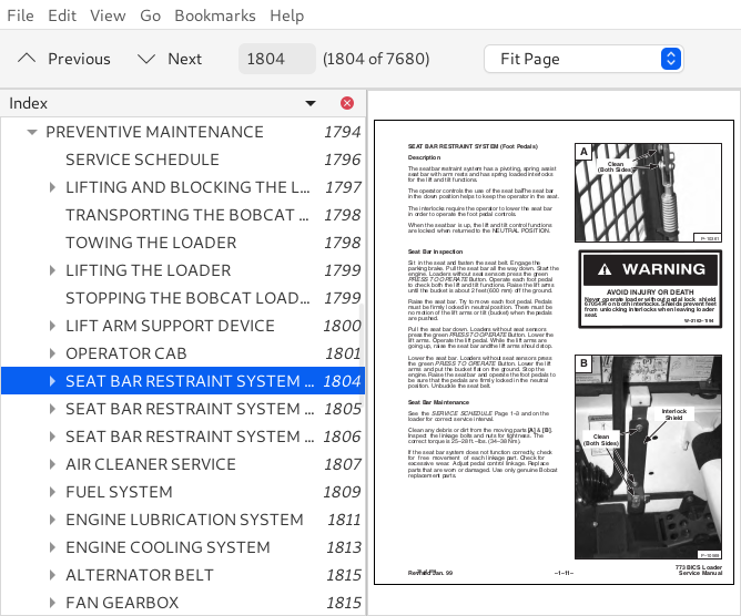
SEAT BAR RESTRAINT SYSTEM (Foot Pedals)...26
Description...26
Seat Bar Inspection...26
Seat Bar Maintenance...26
SEAT BAR RESTRAINT SYSTEM (Mechanical Hand Controls)...27
Description...27
Seat Bar Inspection...27
Seat Bar Maintenance...27
SEAT BAR RESTRAINT SYSTEM (Advanced Hand Controls)...28
Description...28
Seat Bar Inspection...28
Seat Bar Maintenance...28
AIR CLEANER SERVICE...29
Replacing Filter Element...29
FUEL SYSTEM...31
Fuel Specifications...31
Filling The Fuel Tank...31
Fuel Filter...31
Removing Air From The Fuel System...32
ENGINE LUBRICATION SYSTEM...33
Checking Engine Oil...33
Oil Chart...33
Replacing Oil And Filter...33
ENGINE COOLING SYSTEM...35
Cleaning The Cooling System...35
Checking The Coolant Level...35
Replacing The Coolant...36
ALTERNATOR BELT...37
Adjusting The Alternator Belt...37
FAN GEARBOX...37
Checking And Maintaining...37
HYDRAULIC/HYDROSTATIC SYSTEM...38
Checking And Adding Fluid...38
Replacing Hydraulic/Hydrostatic Filter...38
Replacing Hydraulic Fluid...39
Hydraulic Reservoir Breather Cap...40
SPARK ARRESTOR MUFFLER...41
Cleaning Procedure...41
TIRE MAINTENANCE...42
Wheel Nuts...42
Tire Rotation...42
Tire Mounting...42
FINAL DRIVE TRANSMISSION (CHAINCASE)...43
Checking And Adding Oil...43
Replacing Oil In The Chaincase...43
DRIVE BELT...44
Adjusting The Drive Belt Equipped With The Spring Loaded Drive Idler...44
Adjusting The Drive Belt Equipped With The Fixed Drive Idler...46
Drive Belt Replacement...47
LUBRICATION OF THE BOBCAT LOADER...48
Procedure...48
BOB–TACH...50
Inspection And Maintenance...50
REMOTE START SWITCH...51
Procedure...51
HYDRAULIC SYSTEM...53
HYDRAULIC/HYDROSTATIC SCHEMATICS...57
TROUBLESHOOTING...85
HYDRAULIC SYSTEM INFORMATION...86
Tightening Procedure...86
LIFT CYLINDER(S)...87
Checking The Lift Cylinder(s) For Internal Leakage...87
Removal And Installation...87
TILT CYLINDER...88
Checking The Tilt Cylinder For Internal Leakage...88
Removal And Installation...88
Rod End Seal Replacement...89
HYDRAULIC CYLINDER IDENTIFICATION...90
Lift Cylinder Components...90
Tilt Cylinder Components...91
HYDRAULIC CYLINDERS...92
Disassembly...92
Assembly...94
BICS™ VALVE (S/N 512220298 & Above, 512440721 & Above and 512612258 & Above)...100
Removal...100
Lift Arm By–Pass Orifice Disassembly...101
Check Valve Disassembly...101
Lock Valve Disassembly...102
BICS™ Valve Solenoid Disassembly...103
BICS™ Valve Solenoid Assembly...104
Lock Valve Assembly...105
Check Valve Assembly...105
Lift Arm By–Pass Orifice Assembly...106
Installation...107
CONTROL VALVE (S/N 512220298 & Above, 512440721 & Above and 512612258 & Above)...108
Removal And Installation...108
Identification Chart...111
Disassembly...112
Lift Base End Restrictor Disassembly...112
Load Check Valve Disassembly...112
Main Relief Valve Disassembly...113
Port Relief Valve Disassembly...114
Anti–Cavitation Valve Disassembly...115
Rubber Boot Disassembly...116
Lift Spool And Detent Disassembly...117
Tilt Spool And Centering Spring Disassembly...120
Auxiliary Spool Disassembly...122
Auxiliary Electric Solenoid Disassembly...123
Port–Auxiliary Section Disassembly...124
Cleaning And Inspection...124
Port–Auxiliary Section Assembly...125
Auxiliary Electric Solenoid Assembly...125
Auxiliary Spool Assembly...126
Tilt Spool And Centering Spring Assembly...127
Lift Spool And Detent Assembly...129
Rubber Boot Assembly...131
Anti–Cavitation Valve Assembly...132
Port Relief Valve Assembly...133
Main Relief Valve Assembly...134
Load Check Valve Assembly...134
Spool Seal Installation...136
CONTROL VALVE (S/N 512220297 & Below,512440720 & Below and 512612257 & Below)...137
Removal And Installation...137
Identification Chart...140
Disassembly And Assembly...141
Load Check Valve...141
Main Relief Valve...142
Port Relief Valve...142
Anti–Cavitation Valve...143
Rubber Boot...144
Lift Spool Detent...145
Tilt Centering Spring...149
Auxiliary Spool...150
Auxiliary Electric Solenoid...151
Plug/Port Relief Valve...152
Inspection...152
Identification And Installation Of Spool Seal...153
MAIN RELIEF VALVE...154
Checking...154
Adjustment...155
Removal And Installation...155
HYDRAULIC PUMP...156
Removal And Installation...156
Checking The Output Of The Hydraulic Pump...158
Checking The Output Of The High Flow Hydraulic Pump (763H)...160
Disassembly And Assembly...161
Inspection...163
Identification...163
Removal And Installation (763H)...164
Identification (763H)...167
Disassembly And Assembly (763H)...168
HYDRAULIC FILTER HOUSING...171
Removal And Installation...171
HYDRAULIC FLUID RESERVOIR...172
Removal And Installation...172
CONTROL PEDALS...173
Removal And Installation...173
Pedal Adjustment...173
SELECT VALVE (763H)...174
Checking the Main Relief Valve in High Horsepower Select Valve...174
Removal And Installation...175
Disassembly And Assembly (New Style Valve)...177
Solenoid Testing (New Style Valve)...178
Disassembly And Assembly (Old Style Valve)...179
Solenoid Testing (Old Style Valve)...180
PEDAL INTERLOCK LINKAGE...181
Removal And Installation...181
Adjustment...182
LIFT LOCK BY–PASS VALVE...183
Removal And Installation (S/N 512220298 & Above, S/N 512440721 & Above, S/N 512612258 & Above)...183
Removal And Installation (S/N 512220297 & Below, S/N 512440720 & Below, S/N 512612257 & Below)...185
Disassembly And Assembly (S/N 512220297 & Below, S/N 512440720 & Below, S/N 512612257 & Below)...186
TILT LOCK VALVE...187
Removal And Installation (S/N 512220297 & Below, S/N 512440720 & Below, S/N 512612257 & Below)...187
Disassembly And Assembly (S/N 512220297 & Below, S/N 512440720 & Below, S/N 512612257 & Below)...189
HYDROSTATIC SYSTEM...191
TROUBLESHOOTING...193
HYDROSTATIC SYSTEM INFORMATION...194
Replenishing Valve Function...194
Checking Charge Pressure...194
CONTROL PANEL...195
Removal And Installation...195
Steering Shock Removal And Installation...196
Steering Shaft Removal And Installation...196
Steering Shaft Disassembly And Assembly...196
Steering Lever Removal And Installation...197
Rubber Boot Replacement...197
STEERING LINKAGE...198
Removal And Installation...198
Steering Linkage Adjustment...200
Steering Neutral Adjustment...202
HYDROSTATIC DRIVE MOTOR...204
Removal And Installation...204
Identification (S/N 512218843 & Below, S/N 512612191 & Below & S/N 512440645 & Below)...205
Disassembly And Assembly (S/N 512218843 & Below, S/N 512612191 & Below & S/N 512440645 & Below)...206
nspection (S/N 512218843 & Below, S/N 512612191 & Below & S/N 512440645 & Below)...211
Timing The Hydrostatic Motor (S/N 512218843 & Below, S/N 512612191 & Below & S/N 512440645 & Below)...212
HYDROSTATIC MOTOR 30 SERIES...213
Identification (S/N 512218844 & Above, S/N 512612192 & Above, & S/N 512440646 & Above)...213
Disassembly (S/N 512218844 & Above, S/N 512612192 & Above, & S/N 512440646 & Above)...214
Assembly (S/N 512218844 & Above, S/N 512612192 & Above, & S/N 512440646 & Above)...219
HYDROSTATIC PUMP...225
Removal And Installation...225
Identification MODEL: 763...228
Disassembly And Assembly...230
Inspection...238
Swashplate Pre–Load...240
DRIVE BELT HOUSING...241
Removal And Installation...241
SPRING LOADED DRIVE BELT TENSIONER PULLEY...243
Removal And Installation...243
Identification...244
Disassembly...245
Assembly...246
FIXED DRIVE BELT TENSIONER PULLEY...248
Removal And Installation...248
Identification...249
Disassembly...250
Assembly...252
Checking Pulley End Play...256
OIL COOLER...256
Removal And Installation...256
DRIVE SYSTEM...257
PARKING BRAKE...259
Removal And Installation...259
Disassembly And Assembly...259
PARKING BRAKE DISC...260
Removal And Installation...260
TRACTION LOCK GUIDES...261
Disassembly...261
Assembly...262
CHAINCASE FLUID...264
Removing Oil From The Chaincase...264
CHAINCASE COVERS...265