
John Deere 925 935 945 955 965 975 Combines Workshop Repair Service Manual TM4307 PDF - MJODTM4307.zip
This all-encompassing technical guide delivers electrical schematics for the John Deere Combines 925, 935, 945, 955, 965, and 975, along with every shop detail needed to service, troubleshoot, fix, and overhaul these machines at a professional mechanic's level (covering Diagnostics, Operation, Testing, Repairs, Servicing, and Troubleshooting).
Contained within the John Deere Combines 925, 935, 945, 955, 965, 975 workshop technical service manual you will find:
* Numbered table of contents easy to use so that you can find the information you need fast.
* Detailed sub-steps expand on repair procedure information
* Numbered instructions guide you through every repair procedure step by step.
* Troubleshooting and electrical service procedures are combined with detailed wiring diagrams for ease of use.
* Notes, cautions and warnings throughout each chapter pinpoint critical information.
* Bold figure number help you quickly match illustrations with instructions.
* Detailed illustrations, drawings and photos guide you through every procedure.
* Enlarged inset helps you identify and examine parts in detail.
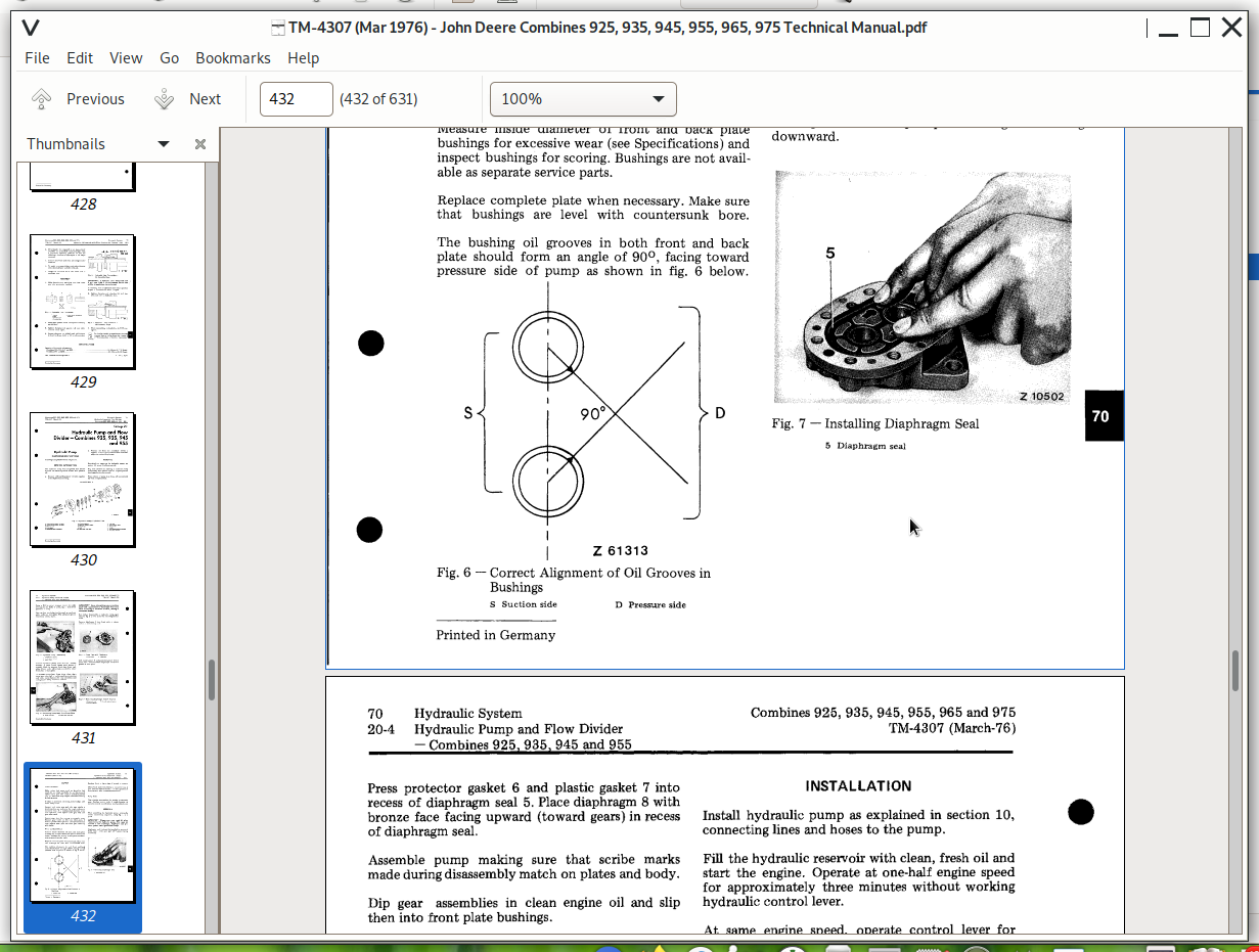
TM-4307 (Mar 1976) - John Deere Combines 925, 935, 945, 955, 965, 975 Technical Manual.pdf
PRODUCT DETAILS:
Total Pages: 631 pages
File Format: PDF (bookmarked, ToC, Searchable, Printable, high quality)
Language: English
TABLE OF CONTENTS
SECTION 10 — GENERAL
Group 5 — Specifications
Group 10 — Pre-delivery, delivery and after-sales inspections
Group 15 ~ Lubrication and periodic service
Group 20 — Engine and combine tune-up
Group 25 — Combine separation
SECTION 20 — ENGINE
Group 5 — General information and diagnosing malfunctions
Group 10 — Cylinder head, camshaft and balancer shafts
Group 15 — Cylinder block, liness, pistons and connecting rads
Group 20 — Crankshaft, main bearings and flywheel
Group 25 — Timing gear train
Group 30 — Engine lubricating system
Group 35 — Engine cooling system
Group 40 — Air intake system
Group 45 — Speed control linkage
SECTION 30 — FUEL SYSTEM
Group 5 — Diagnosing malfunctions
Group 10 — Fuel tank, water trap, transfer pump and fuel filter
Group 15 — Roto Diesel fuel injection pump
Group 20 — Roosa Master fuel injection pump, "DM 4” type
Group 25 — Roosa Master fuel injection nozzles
Group 30 — Cold weather starting aids
SECTION 40 — ELECTRICAL SYSTEM
Group 5 — Diagnosing malfunctions
Group 10 — Components and wiring diagram
Group 15 — Starting motor
Group 20 — Alternator
SECTION 50 — POWER TRAIN 935, 945
Group 5— Engine clutch and ciutch linkage - combines 925,
Group 10 -- Engine clutch and clutch linkage — combine 955
Group 15 — Engine clutch - combines 965 and 975 and 975
Group 16 — Reverser clutch, control and linkage - combines 965, 975
Group 20 — Front Front axle - combines 925, 935 and 945
Group 25 — Front Front axle - combines 955, 965 and 975
Group 30 — Track system - combines 965 and 975
Group 35 — Separator drive
Group 40 — Variable drives
Group 45 — POSIT TORQ ground drive - combine 975
SECTION 60 — BRAKES AND REAR AXLE
Group 5 — Parking brake combines 925, 935, 945
Group 10 — Parking brake - combines 955, 965, 975
Group 15 — Footbrakes
Group 20 — Rear axle
Group 25 — V-support for wide rear axle - combine 975
SECTION 70 — HYDRAULIC SYSTEM
Group 5 — General information, and diagnosing malfunctions
Group 10 — Pressure tests pressure lines
Group 15 — Hydraulic oil reservoir, filter, suction and
Group 20 — Hydraulic purmp and flow drivers
Group 25 — Tandem (dual-gear) hydraulic pump - 965 and 975 combine
Group 30 — Single and three-spool control valves - combines 925 to 955
Group 35 — Seven - spool control valves - combines 965 and 975
Group 40 — Hydraulic cylinders
Group 45 — Nitrogen accumulators
Group 50 — Hydrostatic steering
Group 55 — Hydraulic brakes
Group 60 — Hydraulic clutch control-combines 965 and 975
SECTION 100 — CUTTING PLATFORM AND CORN HEAD
Group 5 — General information and diagnosing malfunctions
Group 10 — Cutting platform and knife drive
Group 15 — Com head
Group 20 — Corn head gear case
SECTION 110 — FEEDER HOUSE
Group 5 — General information and diagnosing malfunctions
Group 10 — Feeder house
SECTION 120 — SEPARATOR AND CLEANING UNIT
Group 5 — General information and diagnosing malfunctions
Group 10 — Threshing Cylinder
Group 15 — Concave
Group 20 — Beater
Group 25 — Cross shaker
Group 30 — Straw walkers, cleaning shoe with sieves and fan
SECTION 130 — ELEVATORS, GRAIN TANK AND GRAIN TANK UNLOADING AUGERS
Group 5 — General information and diagnosing malfunctions
Group 10 — Clean grain auger and elevator
Group 15 — Lower tailings auger, elevator and upper auger
Group 20 — Grain tank leveling auger and unloading augers
Group 25 — Outer unloading auger and housing
John Deere Combines 925, 935, 945, 955, 965, 975 Diagnosis and Repair Service Manual (TM4307)