
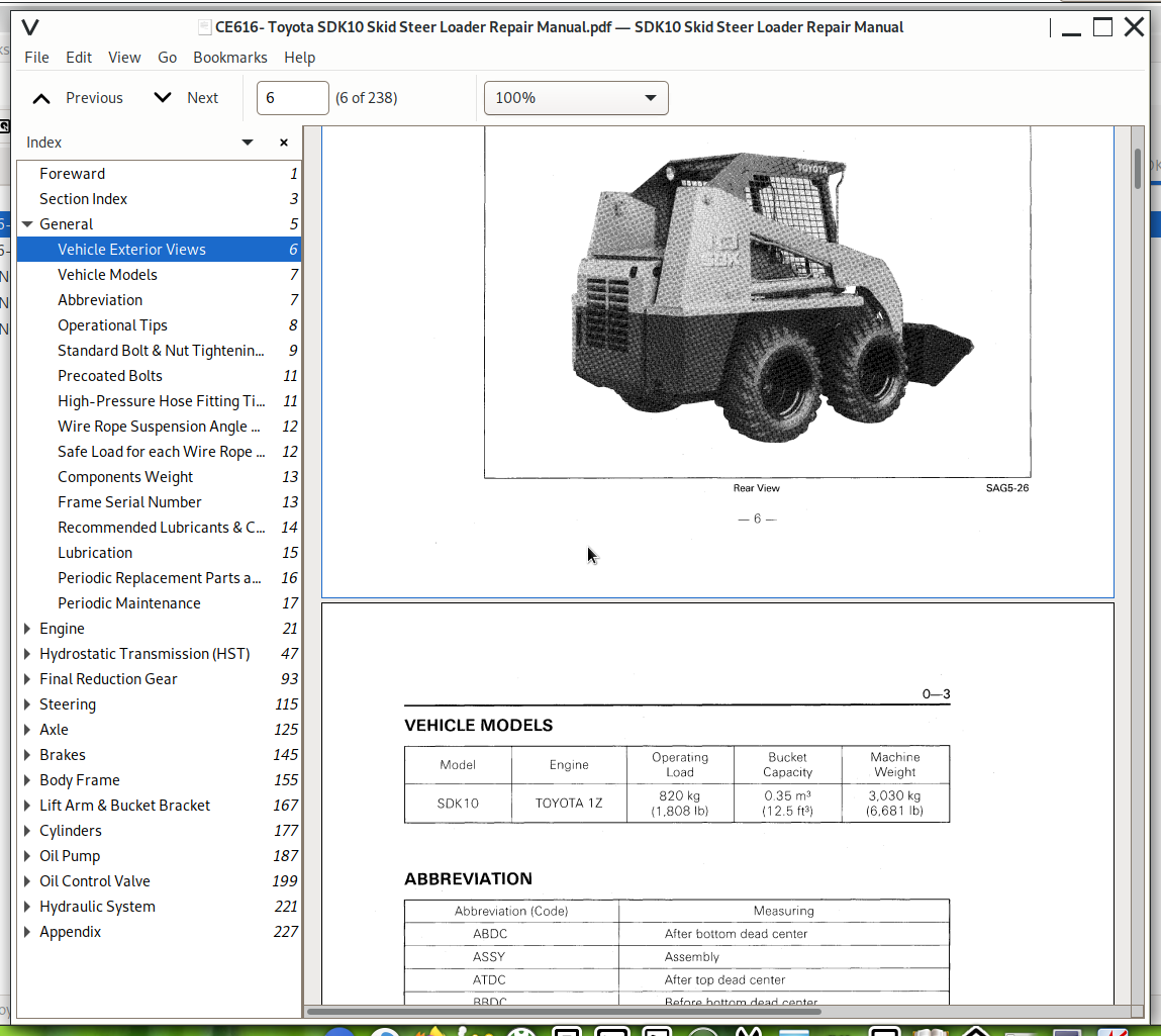
Toyota SDK10 Skid Steer Loader Workshop Repair Service Manual PDF (CE616) - MTOINCE616.zip
Full factory service and repair documentation, complete with electrical wiring diagrams, for the Toyota SDK10 Skid Steer Loader — containing every technical detail needed to service, troubleshoot, fix, and rebuild the machine just like a trained professional technician.
Covered inside the Toyota SDK10 Skid Steer Loader workshop service and repair manual:
* Numbered table of contents easy to use so that you can find the information you need fast.
* Detailed sub-steps expand on repair procedure information
* Numbered instructions guide you through every repair procedure step by step.
* Troubleshooting and electrical service procedures are combined with detailed wiring diagrams for ease of use.
* Notes, cautions and warnings throughout each chapter pinpoint critical information.
* Bold figure number help you quickly match illustrations with instructions.
* Detailed illustrations, drawings and photos guide you through every procedure.
* Enlarged inset helps you identify and examine parts in detail.
PRODUCT DETAILS:
Total Pages: 238 pages
File Format: PDF (Internal Links, Bookmarked, Table of Contents, Searchable, Printable, high quality)
Language: English
CE616 - Toyota SDK10 Skid Steer Loader Repair Manual.pdf
MAIN SECTIONS
Foreward.....1
Section Index.....3
General.....5
Vehicle Exterior Views.....6
Vehicle Models.....7
Abbreviation.....7
Operational Tips.....8
Standard Bolt & Nut Tightening Torque.....9
Precoated Bolts.....11
High-Pressure Hose Fitting Tightening Torque.....11
Wire Rope Suspension Angle List.....12
Safe Load for each Wire Rope Suspension Angle.....12
Components Weight.....13
Frame Serial Number.....13
Recommended Lubricants & Capacities.....14
Lubrication.....15
Periodic Replacement Parts and Lubricants.....16
Periodic Maintenance.....17
Engine.....21
General.....22
Specifications.....24
Engine Assy.....25
Removal.....25
Installation.....34
Air Bleeding from Fuel System.....35
Water Draining from Sedimenter.....35
Engine Speed Adjustment.....36
Accelerator.....37
Components.....37
Accelerator Lever Adjustment.....38
Air Cleaner.....39
General.....39
Components.....40
Specifications.....40
Inspection.....41
Radiator.....43
Components.....43
Specifications.....43
Battery.....44
Components.....44
Specifications.....44
Inspection.....45
Hydrostatic Transmission (HST).....47
General.....48
Components.....49
Speicifcations.....53
Hydraulic Circuit Diagram.....54
Hydraulic Pressure Piping Diagram.....55
Trouble-Shooting.....56
HST Pump Assy.....59
Removal.....59
Disassembly.....61
Inspection.....67
Assembly.....72
Installation.....78
HST Motor Assy.....79
Removal.....79
Disassembly.....81
Inspection.....83
Assembly.....85
Installation.....87
Damage of Rotating Parts & Wear Limits.....88
HST Oil Filter.....91
Removal.....91
Installation.....91
Charge Pressure Measurement.....91
Relief Pressure Measurement.....91
Final Reduction Gear.....93
General.....94
Components.....95
Specifications.....96
Drive Chain Assy.....97
Removal.....97
Inspection.....99
Installation.....99
Drive Unit.....101
Removal.....101
Disassembly.....104
Inspection.....108
Assembly.....109
Installation.....113
Steering.....115
General.....116
Spring Holder.....117
Specifications.....117
Components.....118
Steering Lever.....119
Removal.....119
Spring Holder.....120
Disassembly.....120
Inspection.....121
Assembly.....121
Steering Neutral Adjustment.....123
Troubleshooting for Steering Neutral Adjustment.....124
Axle.....125
General.....126
Components.....127
Specifications.....128
Front Axle Shaft.....129
Removal.....129
Inspection.....132
Installation.....133
Rear Axle Shaft.....137
Removal.....137
Inspection.....140
Installation.....140
Brakes.....145
General.....146
Components.....147
Specifications.....148
Disc Brake.....149
Removal.....149
Inspection.....150
Assembly.....150
Installation.....151
Parking Brake Lever.....152
Removal.....152
Installation.....152
Brake Link.....153
Adjustment.....153
Parking Brake.....154
Adjustment.....154
Brake Pedal.....154
Adjustment.....154
Body Frame.....155
Components.....156
Seat Bar.....162
Components.....162
Adjustment.....163
Lift Arm & Bucket Bracket.....167
Description.....168
Components.....169
Lift Arm.....171
Removal.....171
Installation.....173
Bucket Bracket.....174
Disassembly.....174
Installation.....174
Inspection.....175
Cylinders.....177
Description.....178
Specifications.....178
Components.....179
Dump Cylinder Assy.....181
Removal.....181
Disassembly.....181
Inspection.....182
Assembly.....183
Installation.....183
Lift Cylinder Assy.....184
Removal.....184
Disassembly and Inspection.....186
Assembly and Installation.....186
Oil Pump.....187
Description.....188
Specifications.....188
Components.....189
Oil Pump Assy.....190
Removal.....190
Disassembly.....192
Inspection.....194
Assembly.....196
Installation.....197
Testing Method.....198
Oil Control Valve.....199
Oil Control Valve Assy.....200
General.....200
Component.....204
Removal.....205
Disassembly.....206
Inspection.....210
Assembly.....210
Installation.....210
Relief Pressure Adjustment.....211
Oil Control Valve Link.....212
Component.....212
Pedal Lock System.....213
Solenoid.....214
Specification.....214
Inspection.....214
Self Level Valve Assy.....215
General.....215
Component.....217
Specification.....218
Removal.....218
Disassembly.....219
Inspection.....219
Assembly.....220
Installation.....220
Hydraulic System.....221
Hydraulic Piping.....222
Bleeding Air from Hydraulic Circuit.....225
Hydraulic Circuit Diagram.....226
Appendix.....227
SST List.....228
Service Standards.....231
Wiring Diagram.....237
Toyota SDK10 Skid Steer Loader Repair Service Manual (CE616)