
John Deere 5080R 5090R 5100R 5080RN 5090RN 5100RN Tractor Diagnostics & Tests Workshop Manual with Wiring Diagrams (TM401719) - MJODTM401719.zip
A Complete Diagnostics & Tests service manual featuring Electrical Wiring Diagrams for the John Deere 5080R, 5090R, 5100R, 5080RN, 5090RN, and 5100RN Tractors (European Models, 2WD/MFWD), packed with every piece of shop data you need to service, troubleshoot, and rebuild these machines the way professional technicians do.
Covered within this workshop Diagnosis & Tests manual for John Deere Tractors 5080R, 5090R, 5100R, 5080RN, 5090RN, and 5100RN:
* Numbered table of contents easy to use so that you can find the information you need fast.
* Detailed sub-steps expand on repair procedure information
* Numbered instructions guide you through every repair procedure step by step.
* Troubleshooting and electrical service procedures are combined with detailed wiring diagrams for ease of use.
* Notes, cautions and warnings throughout each chapter pinpoint critical information.
* Bold figure number help you quickly match illustrations with instructions.
* Detailed illustrations, drawings and photos guide you through every procedure.
* Enlarged inset helps you identify and examine parts in detail.
TM401719 - John Deere Tractor 5080R, 5090R, 5100R, 5080RN, 5090RN, 5100RN Technical Manual (Diagnosis & Test).PDF
TM401719 - John Deere Tractor 5080R, 5090R, 5100R, 5080RN, 5090RN, 5100RN Technical Manual (Diagnosis & Test).epub
Total Pages: 2,956 pages
File Format: PDF/EPUB/MOBI/AZW (PC/Mac/Android/Kindle/iPhone/iPad; bookmarked, ToC, Searchable, Printable)
Language: English
MAIN SECTIONS
Foreword
General Information
Safety
General References
Diagnostic Trouble Codes
BCU Control Unit
BIF Control Unit
ECU Control Unit
EPC Control Unit
PRF Control Unit
Observable Symptoms
Electronics
Electronic Control Units
PowrQuad and PowrQuad Plus Transmissions
Drive Systems
Steering and Brakes
Hydraulic system
Miscellaneous
Operator's Cab
System Diagnostics
Electronics
PowrQuad Transmission
Hydraulic system
Engine
General Information
Operational Checks
Tests and Adjustments
Fuel, Air Intake and Cooling Systems
Tests and Adjustments
Fuel System
Air Intake System
Cooling System
Cold Start Aids
Electrical System
Starting Motor and Charging Circuit
Fuel Preheater
Electrical Starting Aid
BIF Control Unit (Basic Informator)
Horn
Operator's Seat and Cigarette Lighter
Lights
Worklights
Connector for Accessories
Radio, Dome Light and Console Light
Air Conditioning and Fan
Windshield Wiper and Washer
Rear Window Wiper and Washer
Beacon Light
3-Terminal and 7-Terminal Power Outlet Sockets (ECE)
BCU Control Unit (Electronic Hitch Control)
BCU Control Unit (Basic Functions)
Signal Socket and Service Socket
PRF Control Unit (Performance Monitor)
CAN BUS Terminating Resistor
Level 16 ECU Control Unit (Electronic Engine Control) for 2-Valve Engine with HPCR
Backup Alarm
EPC (Transmission Control with PowrQuad Plus or AutoQuad Plus Transmission)
Prewiring for GreenStar
Component Information - Connectors and Contacts
Component Information - Connectors (X001 to X249)
Component Information - Connectors (X250 to X499)
Component Information - Connectors (X500 to X749)
Component Information - Connectors (X750 to X999)
Component Information - Connectors (X1000 to X1249)
Component Information - Connectors (XGND)
Component Information - Wiring Harnesses
Component Information - Electrical Parts/Components
Component Information - Electrical Parts/Components (Actuators)
Component Information - Electrical Parts/Components (Sensors/Switches/Potentiometers)
Component Information - Electrical Parts/Components (Fuses/Relays/Diodes)
Component Information - Electrical Parts/Components (Headlamps/Lights)
Component Information - Electrical Parts/Components (Other)
Component Information - Ground Connections
Component Information - CAN BUS System
Electronic Control Units
Operation and General Information on Diagnostics
Interactive Tests
Interactive Calibrations
Information on How to Reprogram Control Units
Data BUS Systems
BCU Control Unit
BIF Control Unit
ECU Control Unit
EPC Control Unit
PRF Control Unit
PowrQuad Transmission
Operational Checks
Tests and Adjustments
Theory of Operation
Drive Systems
Operational Checks
Tests and Adjustments
Front-Wheel Drive Clutch
Differential
Final Drives
Rear PTO Options
Front PTO
Steering and Brakes
Troubleshooting
Operational Checks
Tests and Adjustments
Hydrostatic Steering
Brake Valve
Rear Brakes
Park Brake
Air Brakes
Hydraulic Trailer Brake
Hydraulic System
Operational Checks
Tests and Adjustments
PC Hydraulic System - Theory of Operation
PC Hydraulic System - Oil Filter and Hydraulic Pump
PC Hydraulic System - Hitch
Selective Control Valves (SCVs)
PC Hydraulic System - Priority Valve Block
Miscellaneous
Operational Checks
Tests and Adjustments
Theory Of Operation
Operator's Cab
Operational Checks
Tests and Adjustments
Heating and Ventilation
Air-Conditioning System
Special Tools
Special Tools (Dealer-Fabricated)
Special Tools (Available as Spare Parts)
tm401719 - 5080R-5100R and 5080RN-5100RNTractorsDiagnostics
Table of Contents
Foreword
Section 210: General Information
Group 05: Safety
Safety Information
Recognize Safety Information
”Important” Information
”Note” Information
Prevent Machine Runaway
Handle Fluids Safely—Avoid Fires
Prevent Battery Explosions
Prepare for Emergencies
Prevent Acid Burns
Avoid High-Pressure Fluids
Service Cooling System Safely
Remove Paint Before Welding or Heating
Avoid Heating Near Pressurized Fluid Lines
Work In Ventilated Area
Wear Protective Clothing
Practice Safe Maintenance
Park Machine Safely
Use Proper Lifting Equipment
Construct Dealer-Made Tools Safely
Support Machine Properly
Work in Clean Area
Illuminate Work Area Safely
Service Machines Safely
Use Proper Tools
Service Tires Safely
Service Front-Wheel Drive Tractor Safely
Safety Information - Air Brake System
Avoid Eye Contact With Radar
Keep ROPS Installed Properly
Replace Safety Signs
Dispose of Waste Properly
Live With Safety
Safety Measures on Electronic Control Units
Safety Instructions for Replacing a Halogen Bulb
Safety Instructions for Replacing Xenon (HID) Bulbs and Ballast Units
Group 10: General References
General Information - General References, Summary of References
General Information - Transmission and Hydraulic System, Introductory Checks
General Information - Inch Bolt and Cap Screws, Torque Values
General Information - Metric Bolt and Cap Screws, Torque Values
General Information - Hydraulic System Inch Fittings, Torque Values
General Information - Hydraulic System Metric Fittings, Torque Values
General Information - Electrical System, Component Identification Table
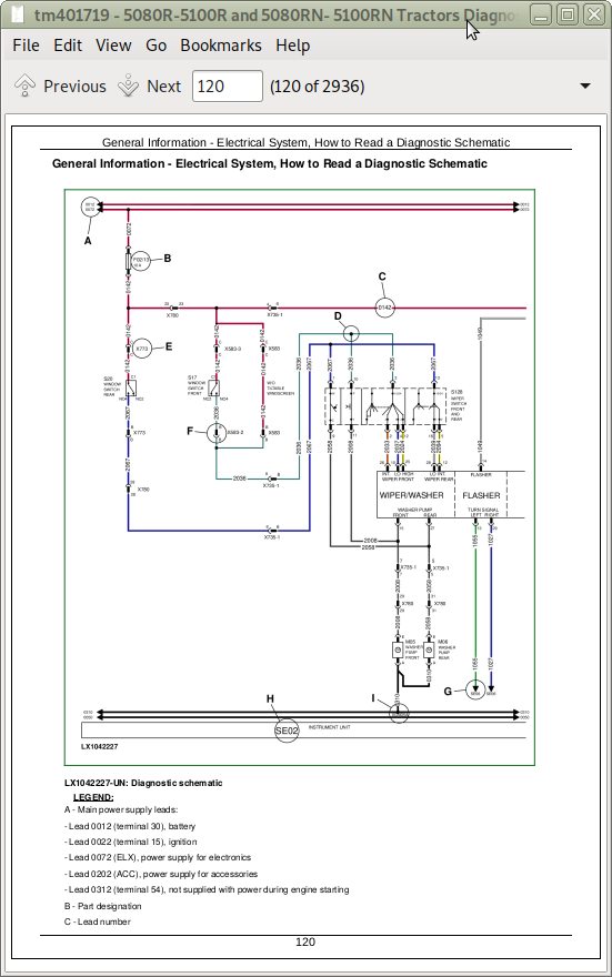
General Information - Electrical System, How to Read a Diagnostic Schematic
General Information - Electrical System, Lead Numbers and Color Codes
General Information - Electrical System, Symbols in Schematic, Wiring and Harness Diagrams
General Information - Electrical System, Troubleshooting Unsolved Problems
General Information - Electrical System, Worksheet for Circuit/Harness Test
General Information - Electrical System, Approach to Tabular Diagnostic Procedures
General Information - Electrical System, Visual Check
General Information - Electrical System, Electrical Circuit Malfunctions
General Information - Electrical System, Seven-Step Test Procedure
General Information - Hydraulic System, Symbols in Circuit Diagrams
General Information - Country Version
Section 211: Diagnostic Trouble Codes
Group BCU: BCU Control Unit
BCU 000084.02 - B35 - Wheel Speed Sensor, Out of Range
BCU 000168.03 - Control Unit, Supply Voltage Too High
BCU 000168.04 - Control Unit, Supply Voltage Too Low
BCU 000168.16 - Control Unit, Supply Voltage Too High
BCU 000168.17 - Control Unit, Supply Voltage Too Low (Engine Speed Above 1500 rpm)
BCU 000168.18 - Control Unit, Supply Voltage Too Low (Engine Speed Above 500 rpm)
BCU 000177.18 - Transmission Oil Temperature Too Low During Calibration
BCU 000186.02 - B06 - Sensor for Rear PTO Speed, Open Circuit
BCU 000186.15 - B06 - Rear PTO Speed Sensor, Speed Present Despite Rear PTO Being Switched Off
BCU 000186.17 - B06 - Rear PTO Speed Sensor, Speed Not Present
BCU 000190.02 - B72 - Crankshaft Speed Sensor, Open Circuit
BCU 000237.02 - VIN Information, Mismatch
BCU 000237.14 - VIN Information, System Deactivated
BCU 000237.31 - VIN Information, Incorrect
BCU 000629.12 - Control Unit Internal Fault
BCU 000639.12 - Vehicle CAN BUS, High Error Rate
BCU 000639.14 - Vehicle CAN BUS, Very High Error Rate
BCU 000746.31 - Y05 - Differential Lock Solenoid Valve, Fault
BCU 000980.07 - S21 - Rear PTO Switch, Fault
BCU 001058.18 - INFORMATION FOR OPERATOR: Pressure Switch for Air-Brake System Is Not Activated (Pressure Too Low)
BCU 001504.14 - INFORMATION FOR OPERATOR: Operator Presence Switch Not Activated While HMS is Selected
BCU 001873.03 - B21 - Hitch Position Sensor, Voltage Too High
BCU 001873.04 - B21 - Hitch Position Sensor, Voltage Too Low
BCU 001873.15 - B21 - Hitch Position Sensor, Voltage Too High During Calibration
BCU 001873.17 - B21 - Hitch Position Sensor, Voltage Too Low During Calibration
BCU 001882.02 - B58 - Sensor for Front PTO Speed, Open Circuit
BCU 001882.15 - B58 - Front PTO Speed Sensor, Speed Present Despite Front PTO Being Switched Off
BCU 001882.17 - B58 - Front PTO Speed Sensor, Speed Not Present
BCU 001883.31 - Rear PTO Speed Too High
BCU 001890.03 - B179 - PTO Shaft Spline Identifier Switch, Supply Voltage Too High
BCU 001890.04 - B179 - PTO Shaft Spline Identifier Switch, Supply Voltage Too Low
BCU 001890.31 - B179 - PTO Shaft Spline Identifier Switch, Fault
BCU 001893.07 - S06 - Front PTO Switch, Fault
BCU 001894.31 - INFORMATION FOR OPERATOR: Rear PTO Switch was On When Engine was Started
BCU 002000.09 - Incorrect CAN BUS Message, Information from ECU
BCU 002003.09 - Incorrect CAN BUS Message, Information from EPC
BCU 002023.09 - Incorrect CAN BUS Message, Information from BIF
BCU 002818.31 - INFORMATION FOR OPERATOR: Operator Presence Switch Not Activated
BCU 002876.07 - S08 - Turn Signal Lever, Fault (Turn Signal)
BCU 303053.03 - B26 - Sensitivity Potentiometer, Signal Voltage Too High
BCU 303053.04 - B26 - Sensitivity Potentiometer, Signal Voltage Too Low
BCU 303056.03 - B27 - Raise-Limit Potentiometer, Signal Voltage Too High
BCU 303056.04 - B27 - Raise-Limit Potentiometer, Signal Voltage Too Low
BCU 303057.03 - B27 - Rate-of-Drop Potentiometer, Signal Voltage Too High
BCU 303057.04 - B27 - Rate-of-Drop Potentiometer, Signal Voltage Too Low
BCU 522507.31 - Control Unit Not Calibrated
BCU 523438.02 - Control Unit Internal Fault
BCU 523652.02 - Control Unit Connected to Wrong Harness Connector
BCU 523689.31 - S22 - Differential Lock Switch, Fault
BCU 523690.02 - S23/S68 - Switches for Remote Control of Hitch (Right/Left), Fault
BCU 523701.05 - M08 - Stepper Motor for Hitch (Coil 2), Open Circuit
BCU 523701.06 - M08 - Stepper Motor for Hitch (Coil 2), Current Too High
BCU 523702.14 - VIN Information, System De-Activated
BCU 523702.31 - VIN Information, Incorrect
BCU 523703.02 - B19 - Right Draft Sensor, Distorted Signal During Calibration
BCU 523703.03 - B19 - Right Draft Sensor, Voltage Too High During Calibration
BCU 523703.04 - B19 - Right Draft Sensor, Voltage Too Low During Calibration
BCU 523703.15 - B19 - Right Draft Sensor, Voltage Too High
BCU 523703.17 - B19 - Right Draft Sensor, Voltage Too Low
BCU 523704.02 - B20 - Left Draft Sensor, Distorted Signal During Calibration
BCU 523704.03 - B20 - Left Draft Sensor, Voltage Too High During Calibration
BCU 523704.04 - B20 - Left Draft Sensor, Voltage Too Low During Calibration
BCU 523704.15 - B20 - Left Draft Sensor, Voltage Too High
BCU 523704.17 - B20 - Left Draft Sensor, Voltage Too Low
BCU 523745.31 - S100 - HMS Program Switch, Fault
BCU 523751.05 - M08 - Stepper Motor for Hitch (Coil 1), Open Circuit
BCU 523751.06 - M08 - Stepper Motor for Hitch (Coil 1), Current Too High
BCU 523753.16 - M08 - Stepper Motor for Hitch, Raising Deadband Too High During Calibration
BCU 523753.18 - M08 - Stepper Motor for Hitch, Raising Deadband Too Low During Calibration
BCU 523756.16 - M08 - Stepper Motor for Hitch, Lowering Deadband Too High During Calibration
BCU 523756.18 - M08 - Stepper Motor for Hitch, Lowering Deadband Too Low During Calibration
BCU 523758.11 - S121 - Remote Control Switch for Rear PTO (Right), Fault
BCU 523759.11 - S44 - Remote Control Switch for Rear PTO (Left), Fault
BCU 523760.04 - Turn Signal/Hazard Flasher System, Supply Voltage Too Low
BCU 523760.31 - Turn Signal/Hazard Flasher System, Fault
BCU 523834.03 - B27 - Depth-Setting Potentiometer, Voltage Too High
BCU 523834.04 - B27 - Depth-Setting Potentiometer, Voltage Too Low
BCU 523839.14 - INFORMATION FOR OPERATOR: Park brake is engaged and a gear is selected
BCU 523839.31 - INFORMATION FOR OPERATOR: Park brake is engaged while wheel speed is detected
BCU 523843.02 - S24 - Quick Raise/Lower Switch, Switch Status Out of Range
BCU 523843.03 - S24 - Quick Raise/Lower Switch, Voltage Too High
BCU 523843.04 - S24 - Quick Raise/Lower Switch, Voltage Too Low
BCU 523904.31 - INFORMATION FOR OPERATOR: Operator Presence Switch Not Activated While Front PTO is Selected
BCU 523905.31 - Y01 - Front PTO Solenoid Valve, Fault
BCU 523908.14 - INFORMATION FOR OPERATOR: Remote Control Switch for Rear PTO is Activated
BCU 523908.31 - S45 - PTO Preselector Switch, Fault
BCU 524055.11 - Control Unit Internal Fault
BCU 524055.31 - Control Unit Not Calibrated
BCU 524216.02 - INFORMATION FOR OPERATOR: Switch Off the Front PTO Switch
BCU 524216.14 - INFORMATION FOR OPERATOR: Switch On the Front PTO Switch.
BCU 524216.31 - INFORMATION FOR OPERATOR: Front PTO was Switched On When Engine Was Started
BCU 524224.02 - INFORMATION FOR OPERATOR: Switch Off the Rear PTO Switch
BCU 524224.14 - INFORMATION FOR OPERATOR: Switch On the Rear PTO Switch.
BCU 524224.31 - INFORMATION FOR OPERATOR: Rear PTO was Switched On When Engine Was Started
BCU 524235.31 - Y03 - Front-Wheel Drive Solenoid Valve, Fault
BCU 524252.31 - Y04 - Solenoid Valve for Rear PTO, Fault