
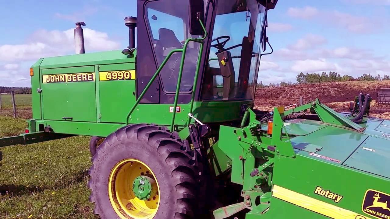
John Deere 4990 Self-Propelled Hay and Forage Windrower Diagnostic & Tests Service Manual (TM1820) - MJODTM1820.zip
The John Deere 4990 Self-Propelled Hay and Forage Windrower Diagnosis & Tests Service Manual (TM1820)
TM1820 – Official John Deere Technical Manual for the 4990 Self-Propelled Hay and Forage Windrower, covering Diagnosis & Tests procedures. Provided in PDF format.
Complete Diagnosis & Tests technical manual with Electrical Wiring Diagrams for John Deere Self-Propelled Hay and Forage Windrowers Models 4990, with all the technical information to maintain, diagnose, rebuild like professional mechanics.
John Deere 4990 Self-Propelled Hay and Forage Windrower workshop Diagnostic, Operation and Tests manual includes:
* Numbered table of contents easy to use so that you can find the information you need fast.
* Detailed sub-steps expand on repair procedure information
* Numbered instructions guide you through every repair procedure step by step.
* Troubleshooting and electrical service procedures are combined with detailed wiring diagrams for ease of use.
* Notes, cautions and warnings throughout each chapter pinpoint critical information.
* Bold figure number help you quickly match illustrations with instructions.
* Detailed illustrations, drawings and photos guide you through every procedure.
* Enlarged inset helps you identify and examine parts in detail.
Total Pages: 2,795 pages
File Format: PDF (bookmarked, ToC, Searchable, Printable, high quality)
Language: English
MAIN SECTIONS
Engine
Fuel/Air Systems
Electrical System Diagnosis and Test (Serial No. -163100)
Electrical Diagrams
Diagnosing Electrical System Malfunctions
Power Supply Circuits Tests
Starting System Tests
Charging System Tests (120 Amp)
Ground Speed Control System Diagnostics
Lighting System Tests
Platform Control Systems Tests
Machine Monitor System Tests
Fuel Control Tests
Heating and Air Conditioning Tests
Cab Accessories Circuits Tests
Air Seat Systems Tests
Miscellaneous Tests
Electrical System Diagnosis and Test (Serial Number 163101 - )
How To Use This Diagnostic Information
Test And Adjustments
Air Condition and Heat Diagnostics
Armrest - Float Pressure Diagnostics
Armrest - Field/Road Shift (Running Lights) Diagnostics
Armrest - Platform Engage Diagnostics
Armrest - Throttle Control Diagnostics
Auxiliary Power Diagnostics
Charging Diagnostics
COMFORT COMMAND Seat Diagnostics
Gauges - Engine Temperature and Fuel Level Diagnostics
Horn Diagnostics
Hydro Handle Diagnostics
Lighting System Diagnostics
Park Brake Diagnostics
Power Distribution Diagnostics
Radio Diagnostics
Rotating Wand Diagnostics
Starting System Diagnostics
Tachometer - Engine Speed and Hourmeter Diagnostics
Tachometer - Float Pressure Diagnostics
Tachometer - Ground Speed/Park Brake Diagnostics
Tachometer - Overall Diagnostics
Tachometer - Platform Speed and Hourmeter Diagnostics
Warning Display Panel
- Alternator Diagnostics
- Engine Air Filter Diagnostics
- Engine Oil Pressure Diagnostics
- Engine Temperature Diagnostics
- Float Pressure Warning Diagnostics
- Hydraulic Oil Filter Diagnostics
- Hydrostatic Charge Pressure Low Diagnostics
- Hydrostatic Oil Temperature Diagnostics
- Low Fuel Diagnostics
- Operator Presence
- Overall Diagnostics
- Park Brake Diagnostics
- Road Shift Engage Light Diagnostics
Wiper Diagnostics
Connector Information (end views, numbers, location photos)
Power Train Diagnosis and Test
Steering and Brakes Diagnosis and Test
Hydraulic System Diagnosis and Test
General Information
Tests and Adjustments
General Hydraulic System Diagnostics
Priority Valve Diagnostics
Open Center Circuit Diagnostics
Platform Raise/Lower Diagnostics
Platform Tilt Diagnostics
Platform Float System Diagnostics
Platform Drive Diagnostics
Auxiliary-Charge Pump Diagnostics
Component Location
Operator Station
tm1820 - 4990 self-propelled windrower
Table of Contents
Foreword
Service Technician Response
Section 210: Safety Information
Group 05: Safety
Recognize Safety Information
Understand Signal Words
Follow Safety Instructions
Handle Fluids Safely-Avoid Fires
Handling Batteries Safely
Prevent Battery Explosions
Prepare for Emergencies
Prevent Acid Burns
Handle Chemical Products Safely
Avoid High-Pressure Fluids
Park Windrower Safely
Stay Clear of Rotating Driveline
Support Machine Properly
Wear Protective Clothing
Work in Clean Area
Service Machines Safely
Work In Ventilated Area
Illuminate Work Area Safely
Replace Safety Signs
Use Proper Lifting Equipment
Service Tires Safely
Remove Paint Before Welding or Heating
Avoid Heating Near Pressurized Fluid Lines
Avoid Harmful Asbestos Dust
Use Proper Tools
Dispose of Waste Properly
Practice Safe Maintenance
Live With Safety
Use Adequate Service Facilities
Practice Safe Service Procedures
Section 220: Engine
Group 10: Diagnostic Information
Diagnose Engine Malfunctions-Use CTM104
Section 230: Fuel/Air Systems
Group 10: Diagnostic Information
Diagnose Fuel and Air Systems Malfunctions-Use CTM104
Section 240: Electrical System Diagnosis and Test (Serial No. -163100)
Group 05: Theory of Operation
Starting System Operation
Charging System Operation
Engine Speed Adjustment Operation
Fuel Shut-Off Circuit Operation
Ground Drive Operation-Hydro Lever In Neutral/Park; Field/Road Switch In Road (Rabbit) Position
Ground Drive Operation-Hydro Lever In Neutral/Park; Field/Road Switch In Field (Turtle) Position
Ground Drive Operation-Hydro Lever Out Of Neutral/Park; Field/Road Switch In Road (Rabbit) Position
Ground Drive Operation-Hydro Lever Out Of Neutral/Park; Field/Road Switch In Field (Turtle) Position
Platform Drive Operation-Engage
Platform Operation-Lower/Raise
Platform Operation-Float and Tilt
Platform Speed Increase/Decrease Operation
Machine Monitor Operation-Warning Display Panel Stop Indicators
Machine Monitor Operation-Warning Display Panel Service Indicators
Machine Monitor Operation-Bulb Test
Machine Monitor Operation-Gauges
Machine Monitor Operation-Digital Display
Cab Accessory Operation-Windshield Wiper And Horn(Serial No. -150000)
Cab Accessory Operation-Windshield Wiper And Horn(Serial No. 150001-163100)
Cab Accessory Operation-Dome Lamp And Radio(Serial No. -163100)
Rotary Wand Air Screen (Serial No. -150000)
Rotary Wand Air Screen (Serial No. 150001-163100)
Air Conditioning System Electrical Operation
Pressurizer and Blower Motor Operation
Lighting System Operation-Daytime Running Lights
Lighting System Operation-Light Switch in 1ST Position (Warning Lamps)
Lighting System Operation-Light Switch in 2ND Position (Road Lamps)
Lighting System Operation-Light Switch in 3RD Position (Field Lamps)
Lighting System Operation-Light Switch in 4TH Position (Additional Field Lamps)
Lighting System Operation-Turn Signals
Group 10: System Information
Multimeter
Fuse and Relay Panel (Power Center)(Serial No. -150000)
Fuse and Relay Panel (Power Center)(Serial No. 150001-163100)
Fuse, Circuit Breaker, And Relay Information
Battery Operation
Diagnose Battery Malfunctions
Using Booster Batteries-12 Volt System
Visually Inspect Electrical System
Electrical Circuit Malfunctions
High Resistance Circuit
Open Circuit
Grounded Circuit
Shorted Circuit
Seven-Step Electrical Test Procedure
Wiring Diagram and Schematic Information
Reading A System Functional Schematic
Electrical Schematic Symbols
Component Identification Table
Wire Color Chart
Group 15: Electrical Diagrams
Electrical Component Identification and Location
Ground Point Locations
Legend For Electrical Schematic (Serial No. -150000)
Electrical Schematic
Legend For Electrical Schematic (Serial No. 150001-163100)
Electrical Schematic
Group 20: Diagnosing Electrical System Malfunctions
Starting Circuit
Engine Speed Adjust
Ground Drive
Parking Brake/Steering Release
Daytime Running Lights
Lighting
Platform Drive
Platform Speed Adjust
Platform Lower/Raise
Platform Float
Platform Tilt
Warning Display Indicators
Cornerpost Gauges
Digital Tach
Alternator/Battery
Relay/Circuit Breaker Panel
Rotating Wand
Heating and A/C
Group 25: Power Supply Circuits Tests
Power Supply Circuits Tests(Serial No. -150000)
Power Supply Circuits Tests(Serial No. 150001-163100)
Group 30: Starting System Tests
Essential or Recommended Tools
Service Equipment and Tools
Starting Circuit Operational Information
Test Battery-Conventional
Test Battery
Test Start Relay
Group 35: Charging System Tests (120 Amp)
Brief Description
Basic Operation
Detailed Description
120 Amp Alternator Diagnostics
Group 40: Ground Speed Control System Diagnostics
Ground Speed Control System Diagnostics
Group 45: Lighting System Tests
Lighting System Circuit Tests-Introduction
Group 50: Platform Control Systems Tests
Platform Control Systems Tests
Group 55: Machine Monitor System Tests
Machine Monitor System Tests
Group 60: Fuel Control Tests
Fuel Control Tests
Group 65: Heating and Air Conditioning Tests
Heating and Air Conditioning Tests
Group 70: Cab Accessories Circuits Tests
Cab Accessories Circuits
Group 75: Air Seat Systems Tests
Air Seat Systems Tests
Group 80: Miscellaneous Tests
Miscellaneous Tests
Miscellaneous Tests
Section 241: Electrical System Diagnosis and Test (Serial Number 163101 - )
Group 05: How To Use This Diagnostic Information
General Information
Group 10: Test And Adjustments
Raising and lowering Platform
Setting Platform Float Alarm
Adjusting Platform Float
Program Tachometer
Group 15A: Air Condition and Heat Diagnostics
Theory of Operation
Electrical Schematic
Air Condition and Heat Diagnostics
Group 15B: Armrest - Float Pressure Diagnostics
Theory of Operation
Electrical Schematic
Armrest - Float Pressure Diagnostics
Group 15C: Armrest - Field/Road Shift (Running Lights) Diagnostics
Theory of Operation
Electrical Schematic
Armrest - Field/Road Shift (Running Lights) Diagnostics
Group 15D: Armrest - Platform Engage Diagnostics
Theory of Operation
Electrical Schematic
Armrest - Platform Engage Diagnostics
Group 15E: Armrest - Throttle Control Diagnostics
Theory of Operation
Electrical Schematic
Armrest - Throttle Control Diagnostics
Group 15F: Auxiliary Power Diagnostics
Theory of Operation
Electrical Schematic
Auxiliary Power Diagnostics
Group 15G: Charging Diagnostics
Theory of Operation
Electrical Schematic
Charging Diagnostics
Group 15H: COMFORT COMMAND COMFORT COMMAND is a trademark of Deere & Company Seat Diagnostics
Theory of Operation
Electrical Schematics
COMFORT COMMAND COMFORT COMMAND is a trademark of Deere & Company Seat Diagnostics
Group 15I: Gauges - Engine Temperature and Fuel Level Diagnostics
Theory of Operation
Electrical Schematic
Gauges - Engine Temperature and Fuel Level Diagnostics
Group 15J: Horn Diagnostics
Theory of Operation
Electrical Schematic
Horn Diagnostics
Group 15K: Hydro Handle - Raise/Lower Diagnostics
Theory of Operation
Electrical Schematic
Hydro Handle Raise/Lower Diagnostics
Group 15L: Hydro Handle - Reel/Platform Speed Diagnostic
Theory of Operation
Electrical Schematic
Hydro Handle - Platform Speed Diagnostic
Group 15M: Hydro Handle - Platform Tilt Diagnostics