
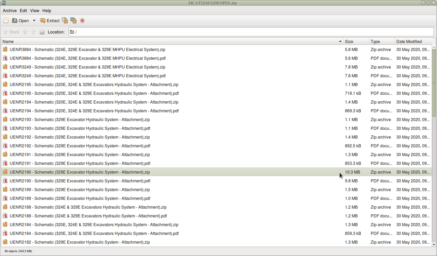
Caterpillar 324E 329E Hydraulic Excavator Workshop Repair Service Manual PDF - MCAT324E329EOPES.zip
Caterpillar 324E & 329E Hydraulic Excavators Repair Service Manuals
This full service and repair manual, complete with Electrical Wiring Diagrams, covers the Caterpillar 324E & 329E Hydraulic Excavators. It contains all the workshop details you need to service, troubleshoot, maintain, and fix these machines the way a professional technician would.
Caterpillar 324E & 329E Hydraulic Excavators workshop service repair manual includes:
* Numbered table of contents easy to use so that you can find the information you need fast.
* Detailed sub-steps expand on repair procedure information
* Numbered instructions guide you through every repair procedure step by step.
* Troubleshooting and electrical service procedures are combined with detailed wiring diagrams for ease of use.
* Notes, cautions and warnings throughout each chapter pinpoint critical information.
* Bold figure number help you quickly match illustrations with instructions.
* Detailed illustrations, drawings and photos guide you through every procedure.
* Enlarged inset helps you identify and examine parts in detail.
PRODUCT DETAILS:
Total Pages: 3,221 pages
File Format: PDF (Internal Links, Bookmarked, Table of Contents, Searchable, Printable, high quality)
Language: English
324E & 329E Hydraulic Excavator Instructor Technical Training Documents
KENR7970 - Testing & Adjusting (312E,F, 313F, 316E,F, 318E,F, 320E,F, 323E,F, 324E, 325F, 326F, 329E,F, 330F, 335F, 336E,F, 340F, 349E,F, 352F, 374F, 390F AC & Heating)
Air Conditioning and Heating System Troubleshooting
Air Conditioning E11 - Intake Air Temperature Sensor (Open Circuit)
Air Conditioning E12 - Intake Air Temperature Sensor (Short Circuit)
Air Conditioning E13 - Ambient Air Temperature Sensor (Open Circuit)
Air Conditioning E14 - Ambient Air Temperature Sensor (Short Circuit)
Air Conditioning E15 - Water Temperature Sensor (Short Circuit)
Air Conditioning E16 - Water Temperature Sensor (Short Circuit)
Air Conditioning E21 - Evaporator Sensor (Open Circuit)
Air Conditioning E22 - Evaporator Sensor (Short Circuit)
Air Conditioning E43 - Air Outlet Damper Error
Air Conditioning E44 - Air Blend Damper Error
Air Conditioning E45 - Air Inlet Damper Error
Air Conditioning Performance - Test
General Troubleshooting Information
Machine Preparation for Troubleshooting
Manifold Gauge Set (Refrigerant) - Install
Manifold Gauge Set (Refrigerant) - Remove
Refrigerant Compressor Oil - Check
Refrigerant Leakage - Test
Refrigerant Recovery
Refrigerant System - Charge
Refrigerant System - Evacuate
Refrigerant System - Flush
Required Tools
Troubleshooting Faults With Service Codes
Visual Inspection
KENR9509 - Systems Operation (E Series Monitor Monitoring System)
Calibration Menu
Configuration Menu
Current Totals Menu
Data Link
Device Test Menu
Diagnostic Menu
Display Setting Menu
ECM Summary Menu
Engine Shutdown Setting Menu
General Information
Input Components
Language Select Menu
Maintenance Intervals Menu
Menu Outline
Override Parameters Menu
Password Change Menu
Password Entry
Performance Menu
Power Mode Setting Menu
Prestart Monitoring Function - If Equipped
Service Menu
Status Menu
System Schematic
Tool Programming Menu
Warning Operation
WinFlash Menu
Work Tool Select Menu
KENR9698 - Systems Operation (320E, 320F, 323E, 323F, 324E, 326F, 329E, 329F & 330F Excavators Tool Control System)
Combined Function - Electric Control
Combined Function - Hydraulic Control
General Information
Medium Pressure Hydraulic System
One-WayOne or Two Pump - Electric Control
One-WayOne or Two Pump - Hydraulic Control
Sensors
Solenoid Valves
Switches
Two-WayOne Pump - Electric Control
Work Tool Parameters - Control Functions
KENR9698 - Testing & Adjusting (320E, 320F, 323E, 323F, 324E, 326F, 329E, 329F & 330F Excavators Tool Control System)
Combined Function - Electric Control Default Value of Work Tool Parameters (1)
Combined Function - Electric Control Default Value of Work Tool Parameters (2)
Combined Function - Electric Control Parameter Adjustment
Combined Function - Electric Control Parameter Setting
Combined Function - Electric Control Relief Valve (Line) - Test and Adjust
Combined Function - Hydraulic Control Default Value of Work Tool Parameters
Combined Function - Hydraulic Control Parameter Adjustment
Combined Function - Hydraulic Control Parameter Setting
Combined Function - Hydraulic Control Relief Valve (Line) - Test and Adjust
Control (Pedal) - Calibrate
Control (Thumb Wheel) - Calibrate
Medium Pressure Default Value of Work Tool Parameters
Medium Pressure Relief Valve (Line) - Test and Adjust
Medium Pressure Relief Valve (Main) - Test and Adjust
One-WayOne or Two Pump - Electric Control Default Value of Work Tool Parameters (1)
One-WayOne or Two Pump - Electric Control Default Value of Work Tool Parameters (2)
One-WayOne or Two Pump - Electric Control Parameter Adjustment
One-WayOne or Two Pump - Electric Control Parameter Setting
One-WayOne or Two Pump - Electric Control Relief Valve (Line) - Test and Adjust
One-WayOne or Two Pump - Electric Control Relief Valve (Line) - Test and Adjust - Tool Relief Valve
One-WayOne or Two Pump - Hydraulic Control Default Value of Work Tool Parameters
One-WayOne or Two Pump - Hydraulic Control Parameter Adjustment
One-WayOne or Two Pump - Hydraulic Control Parameter Setting
One-WayOne or Two Pump - Hydraulic Control Relief Valve (Line) - Test and Adjust
One-WayOne or Two Pump - Hydraulic Control Relief Valve (Line) - Test and Adjust - Tool Relief Valve
Process for Setting Up the Work Tool
Solenoid Valve (Proportional Reducing) - Calibrate - Attachment Valves
Solenoid Valve (Proportional Reducing) - Calibrate - Flow Limit Valves (1)
Solenoid Valve (Proportional Reducing) - Calibrate - Flow Limit Valves (2)
Solenoid Valve (Proportional Reducing) - Calibrate - Pilot Pressure Limit
Solenoid Valve (Proportional Reducing) - Calibrate - Variable Relief Valves
System Identification
Two-WayOne Pump - Electric Control Default Value of Work Tool Parameters
Two-WayOne Pump - Electric Control Parameter Adjustment
Two-WayOne Pump - Electric Control Parameter Setting
Two-WayOne Pump - Electric Control Relief Valve (Line) - Test and Adjust
Work Tool Parameter - Program
Work Tool - Select
KENR9843 - Disassembly & Assembly (324E & 329E Excavators & 329E MHPU Mobile Hydraulic Power Unit C7.1 Engine Supplement)
Aftercooler - Remove and Install
Air Cleaner - Remove and Install
Alternator - Remove and Install
Battery - Remove and Install
Belt Tightener - Remove and Install
Clean Emissions Module - Remove and Install
Combustion Head - Remove and Install - Clean Emissions Module
Cooling System Package (Radiator, Hydraulic Oil Cooler, and Aftercooler) - Remove and Install
Crankshaft Vibration Damper and Pulley - Remove and Install
Diesel Particulate Filter - Install
Diesel Particulate Filter - Remove
Electric Starting Motor - Remove and Install
Electronic Control (ARD Combustion Air) - Remove and Install - Clean Emissions Module
Engine Electronic Control - Remove and Install (1)
Engine Electronic Control - Remove and Install (2)
Engine Front Mount - Remove and Install
Engine Oil Cooler - Remove and Install
Engine Oil Filter and Oil Filter Base - Remove and Install
Engine Oil Pump - Remove and Install
Engine Rear Mount - Remove and Install
Engine - Remove and Install
Exhaust Elbow - Remove and Install
Fan Drive - Remove and Install
Fan - Remove and Install
Fuel Cooler - Remove and Install
Fuel Filter and Base - Remove and Install
Fuel Injection Pump - Install
Fuel Injection Pump - Remove
Fuel Manifold - Remove and Install
Hood - Remove and Install
Hydraulic Oil Cooler - Remove and Install
Ignition Coil - Remove and Install - Clean Emissions Module
Nozzle Heater Harness - Remove and Install - Harness Assembly
Oil Pan - Remove and Install
Pressure Sensor (ARD Combustion Air) - Remove and Install
Pressure Sensor (DPF) - Remove and Install
Radiator - Remove and Install
Refrigerant Compressor - Remove and Install
Refrigerant Condenser - Remove and Install
Relay (ARD Nozzle Heater) - Remove and Install
Soot Antenna - Remove and Install
Soot Sensor - Remove and Install
System Pressure - Release
Temperature Sensor (DPF) - Remove and Install
Turbocharger - Remove and Install - First Stage Turbocharger
Turbocharger - Remove and Install - Second Stage Turbocharger
Water Pump - Remove and Install
Water Separator and Fuel Priming Pump - Remove and Install
Water Temperature Regulator - Remove and Install
KENR9844 - Disassembly & Assembly (324E & 329E Excavators & 329E MHPU Mobile Hydraulic Power Unit Machine Systems)
Accumulator - Remove and Install
Actuator Motor (Air Distributor) - Remove and Install
Auxiliary Pilot Valve (Straight Travel) - Remove and Install
Boom Bearings and Seals - Remove and Install
Boom Cylinder - Remove and Install
Boom - Remove and Install
Bucket Cylinder - Remove and Install
Bucket Linkage Bearings and Seals - Remove and Install
Bucket Linkage - Remove and Install
Bucket - Remove and Install
Cab - Remove and Install
Check Valve (Cooler Bypass) - Remove and Install
Control Manifold (Pilot Oil) - Assemble - Hydraulic Lockout, Swing Brake, Travel with Aluminium Valve Body
Control Manifold (Pilot Oil) - Disassemble - Hydraulic Lockout, Swing Brake, Travel with Aluminium Valve Body
Control Manifold (Pilot Oil) - Remove and Install - Hydraulic Lockout, Swing Brake, Travel
Control Module (Automatic Temperature Control Unit) - Remove and Install
Control Valve (Medium Pressure) - Remove and Install
Counterbalance Valve (Travel) - Assemble
Counterbalance Valve (Travel) - Disassemble
Counterbalance Valve (Travel) - Remove and Install
Counterweight - Remove and Install
Duo-Cone Conventional Seals - Install
Final Drive - Assemble
Final Drive - Disassemble
Final Drive - Install
Final Drive - Remove
Front Idler and Recoil Spring - Install
Front Idler and Recoil Spring - Remove
Fuel Tank - Remove and Install
Gear Pump (Auxiliary) - Remove and Install
Gear Pump (Pilot) - Remove and Install
Heating and Air Conditioning Unit - Remove and Install
Hydraulic Lockout Control - Remove and Install
Hydraulic Tank - Remove and Install
Hydraulic Track Adjusters - Assemble
Hydraulic Track Adjusters - Disassemble
Hydraulic Track Adjusters - Remove and Install
Load Control Valve (Boom Cylinder) - Assemble
Load Control Valve (Boom Cylinder) - Disassemble
Load Control Valve (Boom Cylinder) - Remove and Install
Load Control Valve (Stick Cylinder) - Assemble
Load Control Valve (Stick Cylinder) - Disassemble
Load Control Valve (Stick Cylinder) - Remove and Install
Main Control Valve - Assemble
Main Control Valve - Disassemble
Main Control Valve - Remove and Install
Main Hydraulic Pump - Assemble
Main Hydraulic Pump - Disassemble
Main Hydraulic Pump - Remove and Install
Manual Valve (Auxiliary Shutoff) - Install
Manual Valve (Auxiliary Shutoff) - Remove
Pilot Valve (Joystick) - Assemble
Pilot Valve (Joystick) - Disassemble
Pilot Valve (Joystick) - Remove and Install
Pilot Valve (Travel) - Assemble
Pilot Valve (Travel) - Disassemble
Pilot Valve (Travel) - Remove and Install
Pressure Reducing Valve (Boom Priority) - Remove and Install
Pressure Reducing Valve (Medium Pressure) - Remove and Install
Pressure Switch (Refrigerant Pressure Cutoff) - Remove and Install
Pump Drive Coupling - Remove and Install
Quick Coupler - Remove and Install
Recoil Spring - Assemble
Recoil Spring - Disassemble
Refrigerant Receiver-Dryer - Remove and Install
Relief Valve (Pilot) - Remove and Install
Seat - Remove and Install
Seat Support - Remove and Install
Seat Suspension - Remove and Install
Selector Valve (Alternate Pattern Control) - Remove and Install
Shuttle Valve - Remove and Install - Pilot Oil
Shuttle Valve - Remove and Install - Straight Travel
Solenoid Valve (Auxiliary Circuit) - Remove and Install - Tool Relief
Solenoid Valve (Heavy Lift) - Remove and Install
Solenoid Valve (Negative Flow Control, Proportional Reducing Valve) - Assemble
Solenoid Valve (Negative Flow Control, Proportional Reducing Valve) - Disassemble
Solenoid Valve (Negative Flow Control, Proportional Reducing Valve) - Remove and Install
Solenoid Valve (Two-Way Flow and One PumpTwo Pump) - Remove and Install
Sprocket - Remove and Install
Stick Bearings and Seals - Install
Stick Bearings and Seals - Remove
Stick Cylinder - Remove and Install
Stick - Remove and Install
Storage Box and Covers (Cab) - Remove and Install
Swing Cushion Valve - Assemble - Fine Swing Solenoid
Swing Cushion Valve - Disassemble - Fine Swing Solenoid
Swing Cushion Valve - Remove and Install
Swing Drive - Assemble
Swing Drive - Disassemble
Swing Drive - Install
Swing Drive - Remove
Swing Gear and Bearing - Install
Swing Gear and Bearing - Remove
Swing Motor - Assemble
Swing Motor - Disassemble
Swing Motor - Install
Swing Motor - Remove
Swivel - Assemble
Swivel - Disassemble
Swivel - Install
Swivel - Remove
System Pressure - Release
Track Carrier Roller - Install
Track Carrier Roller - Remove
Track - Connect - Press Fit Master Pin
Track Roller - Install
Track Roller - Remove
Track - Separate - Press Fit Master Pin
Travel Motor - Assemble
Travel Motor - Disassemble
Travel Motor - Install
Travel Motor - Remove
Upper Frame and Undercarriage Frame - Connect
Upper Frame and Undercarriage Frame - Separate
Window Wiper Motor - Remove and Install - Lower
Window Wiper Motor - Remove and Install - Upper
UENR1513 - Specifications (324E Excavator Machine System)
Accumulator (Pilot) (1)
Accumulator (Pilot) (2)
Air Cleaner (1)
Air Cleaner (2)
Air Conditioner Lines
Auxiliary Hydraulic Lines (1)
Auxiliary Hydraulic Lines (2)
Auxiliary Hydraulic Lines (3)
Auxiliary Hydraulic Lines (4)
Auxiliary Hydraulic Lines (5)