


XJW01 LCR Bridge Manual (English) [rev 1.02]
On Sale
$3.00
Pay what you want:
(minimum $3.00)
$
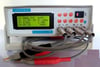
I have written this PDF manual for the XJW01 LCR Bridge (hardware version 3.1, firmware 5.5).
It is written in UK English (not 'Chinglish') and explains what the keys actually do and how to identify, zero, reset, calibrate, save calibration values and use the bridge.
It explains what the values on the LCD display actually mean.
It also includes an example front panel template with the correct button labels.
Note: It does not explain how it works.
Table of Contents
Specifications 3
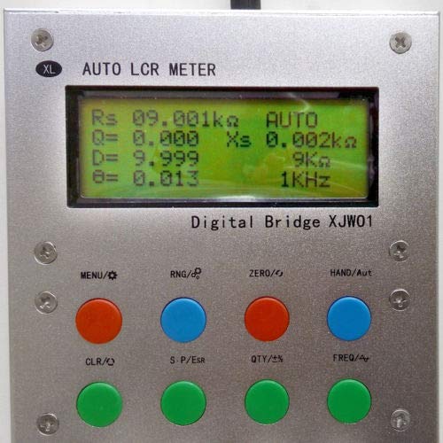
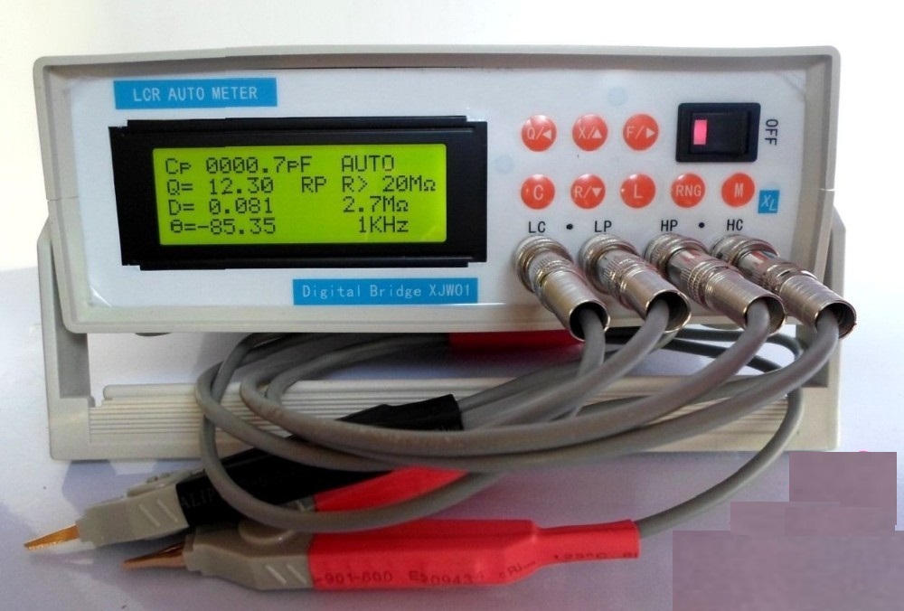
The two types of XJW01 LCR Bridge 5
Keypad keys 6
Hardware 7
Power on 8
‘1602’ Screen (16 characters x 2 lines) 8
‘2004’ Screen (20 characters x 4 lines) 8
Four-line LCD display fields 9
Getting started 9
How to press a key (please read this!) 9
1. Write down the factory calibration settings 9
2. Probe compensation 11
Using the meter 12
1. Automatic measurement 12
2. L/C/R mode 12
3. Series-parallel mode 12
4. Changing the measurement frequency 13
5. Manual mode (HAND) 13
6. Relative measurements (QTY) 14
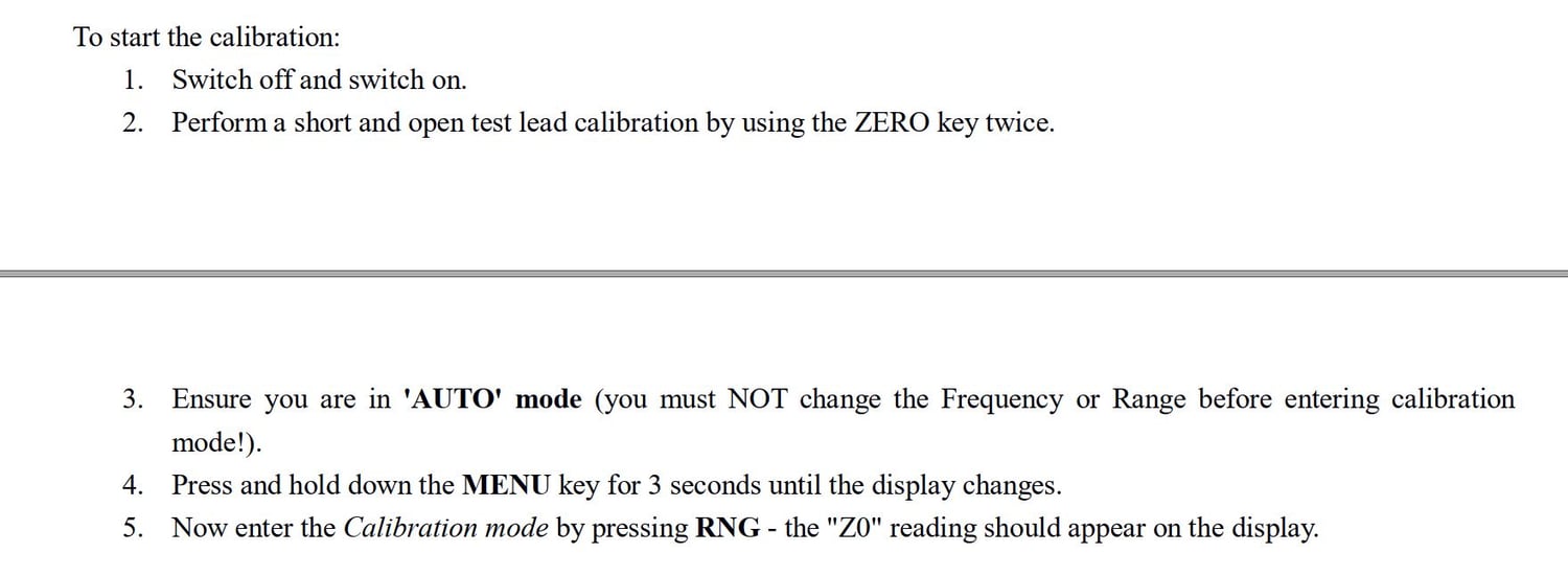
7. Calibration mode (Menu+RNG) 15
7.1 The calibration process 16
7.2 Enter the calibration mode 16
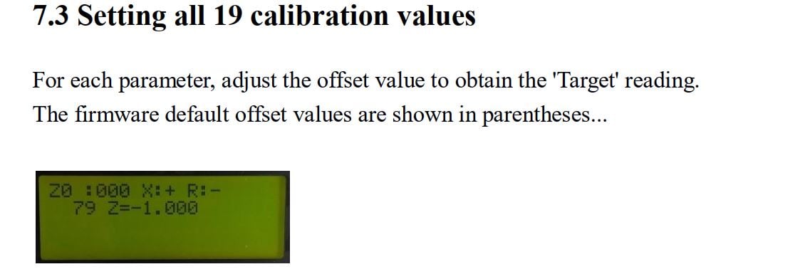
7.3 Setting all 19 calibration values 18
7.4 Save the settings 20
7.5 Reset to firmware defaults 21
Capacitors and ESR (Z) 22
Alternative front panel template (Type 1) 23
Alternative front panel labels (Type 2) 24
Schematics (may be old) 25
Type 1 LCR Bridge PCB 27
Reactance chart 28
It is written in UK English (not 'Chinglish') and explains what the keys actually do and how to identify, zero, reset, calibrate, save calibration values and use the bridge.
It explains what the values on the LCD display actually mean.
It also includes an example front panel template with the correct button labels.
Note: It does not explain how it works.
Table of Contents
Specifications 3
The two types of XJW01 LCR Bridge 5
Keypad keys 6
Hardware 7
Power on 8
‘1602’ Screen (16 characters x 2 lines) 8
‘2004’ Screen (20 characters x 4 lines) 8
Four-line LCD display fields 9
Getting started 9
How to press a key (please read this!) 9
1. Write down the factory calibration settings 9
2. Probe compensation 11
Using the meter 12
1. Automatic measurement 12
2. L/C/R mode 12
3. Series-parallel mode 12
4. Changing the measurement frequency 13
5. Manual mode (HAND) 13
6. Relative measurements (QTY) 14
7. Calibration mode (Menu+RNG) 15
7.1 The calibration process 16
7.2 Enter the calibration mode 16
7.3 Setting all 19 calibration values 18
7.4 Save the settings 20
7.5 Reset to firmware defaults 21
Capacitors and ESR (Z) 22
Alternative front panel template (Type 1) 23
Alternative front panel labels (Type 2) 24
Schematics (may be old) 25
Type 1 LCR Bridge PCB 27
Reactance chart 28