
Mitsubishi Fuso FE FG FK FM 2008-2010 Workshop Repair Service Manual PDF - MMTBSFUSOEM0810OPEK.zip
This is the complete factory-level service and repair manual, featuring Electrical Wiring Diagrams, for the 2008-2010 Mitsubishi Fuso FE, FG, FK, and FM Series trucks. It contains every technical detail needed to service, troubleshoot, fix, and rebuild these vehicles to the same standard as professional technicians.
Included in the 2008-2010 Mitsubishi Fuso FE.FG.FK.FM Series workshop service repair manual:
* Numbered table of contents easy to use so that you can find the information you need fast.
* Detailed sub-steps expand on repair procedure information
* Numbered instructions guide you through every repair procedure step by step.
* Troubleshooting and electrical service procedures are combined with detailed wiring diagrams for ease of use.
* Notes, cautions and warnings throughout each chapter pinpoint critical information.
* Bold figure number help you quickly match illustrations with instructions.
* Detailed illustrations, drawings and photos guide you through every procedure.
* Enlarged inset helps you identify and examine parts in detail.
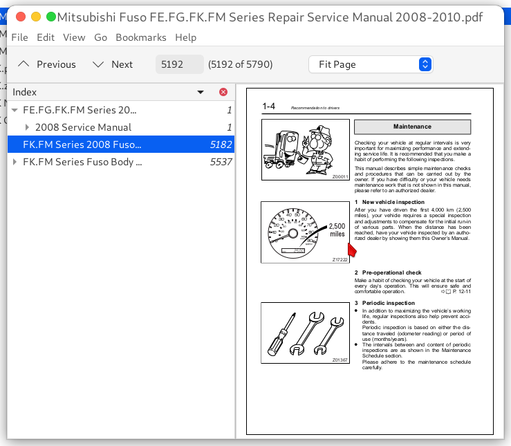
Mitsubishi Fuso FE.FG.FK.FM Series 2008-2010 Service Manual (PWME0806&TWME0709&TWSE0713&TWSE0805).pdf
Mitsubishi Fuso FK.FM Series 2008 Owner's Manual (MH997284).pdf
Mitsubishi Fuso FK.FM Series Body Builder's Drawings & Supporting Data (LTE07001-A - 2007.09).pdf
PRODUCT DETAILS:
Total Pages: 5,790 pages
File Format: PDF (Internal Links, Bookmarked, Table of Contents, Searchable, Printable, high quality)
Language: English
TABLE OF CONTENTS
FE.FG.FK.FM Series 2008-2010 Fuso Service Manual (PWME0806&TWME0709&TWSE0713&TWSE0805)...1
2008 Service Manual...1
2008 FE/FG Service Manual...2
Group 00 - General...3
Table of Contents...4
Equipment Type Codes List...5
Power Train Table...6
How To Read This Manual...7
Chassis Number, Engine Number, Power Train Label...11
Vehicle Identification Number...12
Precautions for Maintenance Operation...13
Jacking Up the Vehicle...25
Diagnosis Codes...27
1. Diagnosis Codes...27
2. Reading and Erasing the Diagnosis Code...28
Table of Standard Tightening Torques...33
Group 01 - Maintenance Schedule...36
Table of Contents...37
How to Read the Maintenance Schedule Tables...38
Maintenance Schedule Tables...40
Maintenance Operations...44
Lubrication Tables...50
Lubrication...52
Group 11 - Engine...56
Table of Contents...57
Specifications...58
Structure and Operation...59
1. Exploded View...59
2. Cylinder Head, Cylinder Head Gasket, Camshaft and Camshaft Frame...60
3. Valve Mechanism...61
4. Connecting Rod...62
5. Piston...62
6. Timing Gears...63
7. Flywheel...63
8. Balance Shafts...64
9. Crankcase and Main Bearings...65
10. Oil Seals...67
Troubleshooting...68
On-Vehicle Inspection and Adjustment...70
1. Measuring Compression Pressure...70
2. Inspection and Adjustment of Valve Clearances...72
3. Removal and Installation of Injector Crew Cab (Fixed Type)...74
Engine Removal and Installation...76
Tilt Cab...76
Fixed Cab...84
Rocker Cover...86
Rockers and Camshafts...88
Cylinder Head and Valve Mechanism...102
Pistons, Connecting Rod and Cylinder Liners...118
Flywheel...132
Front Case...136
Timing Gears and Balance Shafts...140
Crankshaft and Crankcase...148
Balance Shaft Bushings...156
Group 12 - Lubrication...161
Table of Contents...162
Specifications...163
Structure and Operation...164
1. Lubrication System...164
2. Oil Pump...165
3. Oil Cooler...166
4. Oil Filter...167
5. Lubrication of Engine Components...168
Troubleshooting...171
On-Vehicle Inspection and Adjustment...173
1. Oil Filter Replacement...173
2. Engine Oil Replacement...177
3. Engine Oil Level Inspection...179
4. Oil Pressure Measurement...180
Oil Pan, Oil Strainer and Oil Jets...181
Oil Pump...183
Oil Filter...187
Oil Cooler...191
Group 13A - Fuel and Engine Control...193
Table of Contents...194
Specifications...195
Structure and Operation...196
1. Fuel System (Flow of Fuel)...196
2. Engine Control...197
3. Fuel Filter...198
Troubleshooting...199
On-Vehicle Inspection and Adjustment...201
1. Inspecting and Adjusting No-Load Minimum and Maximum Speeds...201
2. Air-Bleeding of Fuel System...202
3. Fuel Filter Replacement...203
Fuel Tank...205
Outside Frame Type...205
Inside Frame Type...207
Fuel Filter...209
Engine Control...213
Common Rail...217
Supply Pump...221
Injector...225
Group 13EA - Common Rail System...228
Table of Contents...229
Specifications...230
Structure and Operation...231
1. Overview...231
2. Electronic Control System...240
3. Electronic Control Unit Connection Diagram...248
Troubleshooting...250
1. Diagnosis Procedure...250
2. Diagnostic Precautions...250
3. Inspection Based on Fault Codes...251
4. Multi-Use Tester Service Data...1192
5. Mode 06 Data...1196
6. Actuator Tests Performed Using Multi-Use Tester...1198
Registration and Alteration of Data In Engine Electronic Control Unit...1202
1. Operation at Electronic Control Unit Replacement...1202
2. Resetting the Diesel Particulate Filter Related Information (Resetting Electronic Control Unit)...1202
Inspection of Electrical Equipment...1204
Installed Locations of Parts...1214
Electric Circuit Diagram...1220
Group 13EB - Auto Cruise and Vehicle Speed Limitation System...1225
Table of Contents...1226
Structure and Operation...1227
1. General Description...1227
2. Electronic Control System...1227
3. Electronic Control Unit Connection Diagram...1231
Troubleshooting...1233
1. Diagnosis Procedure...1233
2. Diagnostic Precautions...1234
3. Inspection Based on Diagnosis Codes...1235
4. Multi-Use Tester Service Data...1239
5. Actuator Tests Performed Using Multi-Use Tester...1240
6. Works Required When Replacing the Multifunction Vehicle Control Unit (MVCU)...1240
7. Inspection Performed at Electronic Control Unit Connectors...1241
Inspection of Electrical Equipment...1242
Installed Locations of Parts...1243
Electric Circuit Diagram...1247
Group 14 - Cooling...1249
Table of Contents...1250
Specifications...1251
Structure and Operation...1253
1. Cooling System (Flow of Coolant)...1253
2. Thermostat...1254
3. Water Pump...1254
Troubleshooting...1255
On-Vehicle Inspection and Adjustment...1257
1. Inspection and Adjustment of Belt Tension...1257
2. Inspection of Cracks or Damage of the Belt...1262
3. Coolant Replacement and Cleaning of Cooling System...1263
4. Air Bleeding of Cooling System...1265
5. Air/Gas Leakage Test...1265
Disconnection and Connection of Hoses and Pipes...1267
Radiator, Fan Shroud...1271
Cooling fan, Belt and Water Pump...1279
Tension Pulley...1282
Thermostat...1283
Pressure Cap and Water Outlet Case...1285
Group 15 - Intake and Exhaust...1287
Table of Contents...1288
Specifications...1289
Structure and Operation...1289
1. Air Cleaner...1289
2. Turbocharger...1290
3. Turbocharger Control System...1291
4. Diesel Particulate Filter Regeneration Control System...1295
Troubleshooting...1305
On-Vehicle Inspection and Adjustment...1307
1. Measurement of Turbocharger Boost Pressure...1307
2. Cleaning and Inspection of Air Cleaner Element...1308
3. Diesel Particulate Filter Unit Inspection for Clogging and Cleaning the Diesel Particulate Filter Unit...1309
4. Resetting the DPF-Related Information (Resetting Electronic Control Unit)...1313
Air Duct and Air Cleaner...1317
Except Crew Cab...1317
Crew Cab...1321
Turbocharger...1325
Intercooler...1331
Intake Manifold...1335
Exhaust Manifold...1337
Exhaust Pipe...1339
Diesel Particulate Filter...1341
Group 17 - Emission Control...1347
Table of Contents...1348
Structure and Operation...1349
1. Exhaust Gas Recirculation System...1349
2. Crankcase Emission Control System...1354
Exhaust Gas Recirculation Valve, Pipe and Cooler...1355
Crankcase Emission Control System...1359
Group 21 - Clutch...1362
Table of Contents...1363
Specifications...1364
Structure and Operation...1365
1. Clutch Control...1365
2. Clutch Master Cylinder...1366
3. Clutch Proper and Clutch Direct Power Cylinder...1368
Troubleshooting...1370
On-Vehicle Inspection and Adjustment...1372
1. Replacement of Brake Fluid (Clutch System)...1372
2. Air Bleeding of Brake Fluid (Clutch System)...1374
3. Inspection of Clutch Disc Wear Limit...1376
Clutch Pedal...1378
Clutch Master Cylinder...1382
Clutch Proper...1384
Clutch Control...1388
Group 22 - Manual Transmission...1393
Table of Contents...1394
Specifications...1395
Structure and Operation...1397
1. Transmission...1397
2. Synchromesh Mechanism...1399
3. Interlock Mechanism...1402
4. Speedometer Gear Bushing...1402
Troubleshooting...1403
On-Vehicle Inspection and Adjustment...1405
1. Inspection of Transmission Oil Leak...1405
2. Inspection of Looseness in Transmission Mounting Bolts...1405
3. Inspection of Play In Companion Flange and Looseness in Lock Nut...1406
4. Inspection and Replacement of Transmission Oil...1406
Removal and Installation of Transmission...1409
Gear Shifter Upper...1413
Rear Cover S5 and Parking Brake...1419
Extension Housing S6 and Parking Brake...1423
Reverse Idler Gear...1429
6th Gear S6...1433
Transmission Body...1439
Drive Pinion...1455
Mainshaft...1457
Countershaft...1467
Transmission Control...1469
Bearing Puller and Installer...1473
Group 23 - Automatic Transmission...1474
Table of Contents...1475
Specifications...1476
Structure and Operation...1477
1. Overview...1477
2. Electronic Control System...1483
3. Electronic Control Unit Connection Diagram...1488
Troubleshooting...1490
1. Diagnosis Procedure...1490
2. Diagnostic Precautions...1490
3. Inspections Based on Diagnosis Codes...1491
4. Multi-Use Tester Service Data...1789
5. Possible Causes of Symptoms...1792
On-Vehicle Inspection and Adjustment...1796
1. Inspection of Automatic Transmission Oil Leakage...1796
2. Check for Looseness in Automatic Transmission Mounting Bolts...1796
3. Inspection of Play in Companion Flange and Looseness in Lock Nut...1797
4. Inspection of Automatic Transmission Fluid...1797
5. Replacement of Automatic Transmission Fluid...1798
6. Stall Test...1800
7. Time Lag Test...1801
8. Line Pressure Test...1802
9. Road Test...1804
10. Dealer Adjust...1805
Removal and Installation of Automatic Transmission...1808
Parking Brake...1814
Automatic Transmission Control...1816
Oil Cooler...1826
Except Crew Cab...1826
Crew Cab...1828
Replacement of Part of Automatic Transmission Main Body...1830
Inspection of Electrical Equipment...1834
Installed Locations of Parts...1838
Electric Circuit Diagram...1842
Group 24 - Transfer...1846
Table of Contents...1847
Specifications...1848
Structure and Operation...1849
1. Transfer...1849
2. Speedometer Gear Bushing...1850
Troubleshooting...1851
On-Vehicle Inspection and Adjustment...1852
1. Inspection of Looseness in Transmission and Transfer Mounting Bolts...1852
2. Inspection of Play and Looseness in Companion Flange...1852
3. Inspection and Replacement of Transfer Oil...1853
Removal and Installation of Transmission (With Transfer)...1854
Removal and Installation of Transfer...1858
Front Drive...1860
Rear Drive...1866
Transfer...1872
Transfer Control (High-Low Switching)...1880
Group 25 - Propeller Shaft...1884
Table of Contents...1885
Specifications...1886
Structure and Operation...1886
1. Configuration of Propeller Shaft Connection...1886
2. Propeller Shaft Without Center Bearing...1887
3. Propeller Shaft With Center Bearing...1888
Troubleshooting...1889
Removal and Installation of Propeller Shaft...1890