
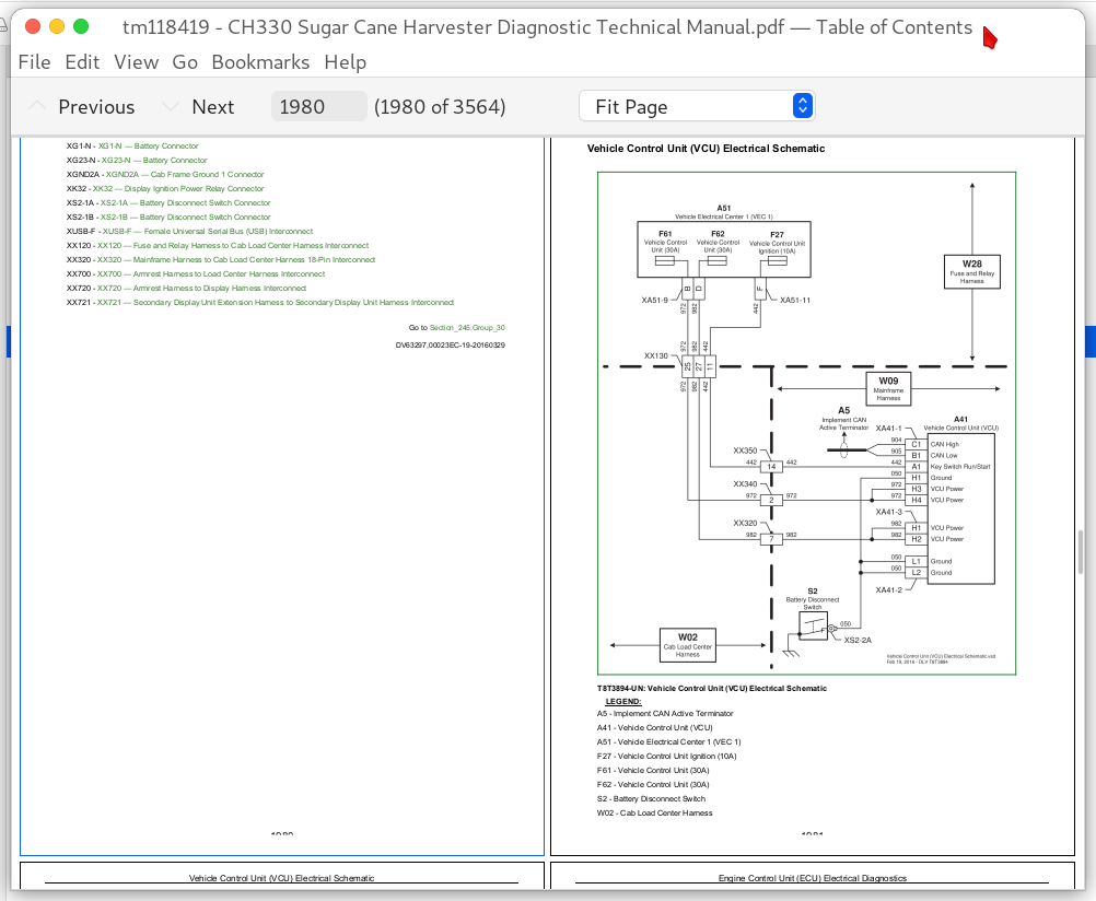
John Deere CH330 Sugar Cane Harvester (SN 121901-) T8 Diagnosis & Tests Service Manual TM118419 PDF - MJODTM118419.zip
Full service diagnostic and testing guide, complete with electrical wiring schematics, for John Deere Sugar Cane Combines bearing the PIN prefix T8 (Thibodaux series), covering model CH330 from serial number 121901 onward. Inside you'll find every technical detail needed to service, troubleshoot, fix, and overhaul your machine to professional-shop standards.
The John Deere CH330 Sugar Cane Harvester Operation & Tests shop manual contains:
* Numbered table of contents easy to use so that you can find the information you need fast.
* Detailed sub-steps expand on repair procedure information
* Numbered instructions guide you through every repair procedure step by step.
* Troubleshooting and electrical service procedures are combined with detailed wiring diagrams for ease of use.
* Notes, cautions and warnings throughout each chapter pinpoint critical information.
* Bold figure number help you quickly match illustrations with instructions.
* Detailed illustrations, drawings and photos guide you through every procedure.
* Enlarged inset helps you identify and examine parts in detail.
TM118419 - John Deere CH330 Sugar Cane Combines Technical Manual (Diagnosis and Tests).PDF
TM118419 - John Deere CH330 Sugar Cane Combines Technical Manual (Diagnosis and Tests).epub
Total Pages: 3,561 pages
File Format: PDF/EPUB/MOBI/AZW (PC/Mac/Android/Kindle/iPhone/iPad; bookmarked, ToC, Searchable, Printable)
Language: English
MAIN SECTIONS
Foreword
General Information
Safety
General References
Technical References
Diagnostic Trouble Codes
Engine Control Unit (ECU) Diagnostic Trouble Codes
Primary Display Unit (PDU) Diagnostic Trouble Codes
Power Control Unit (PTP) Diagnostic Trouble Codes
Vehicle Control Unit (VCU) Diagnostic Trouble Codes
CommandCenter (VTI) Diagnostic Trouble Codes
Observable Symptom and System Diagnostics
Engine
Fuel, Air Intake, Exhaust and Cooling Systems
Electrical System
Electronic Control Units
Power Train
Steering and Brakes
Hydraulic System
Engine
General Information
Theory of Operation
Schematics
Tests and Adjustments
Fuel, Air Intake, Exhaust and Cooling
General Information
Operational and Preliminary Checks
Theory of Operation
Schematics
Tests and Adjustments
Electrical System
General Information
Operational and Preliminary Checks
Theory of Operation
Schematics
Tests and Adjustments
Electronic Control Units
General Information
Operational and Preliminary Checks
Interactive Tests and Calibrations
SDUA Readings
Programming Electronic Control Units
Theory of Operation
Schematics
Tests and Adjustments
Engine Control Unit (ECU) Software Addresses
Power Train Propulsion (PTP) Control Unit Software Addresses
Primary Display Unit (PDU) Software Addresses
Vehicle Control Unit (VCU) Software Addresses
CommandCenter (VTI) Software Addresses
Electrical Component Information
Electrical Assemblies
Sensors
Lights
Fuses
Charging
Monitoring Devices
Relays
Motors
Resistors
Switches
Diodes
Wiring Harnesses
Interconnects and Ground Points
Electronically Actuated Mechanical Devices
Hydrostatic Drive
Theory of Operation
Schematics
Diagnostic Procedures
Diagnostic Tests
Powertrain Component Information
Hydrostatic Drive Components
Steering and Brakes
General Information
Operational and Preliminary Checks
Theory of Operation
Schematics
Diagnostic Procedures
Diagnostic Tests
Steering and Brakes Component Information
Steering Components
Park Brake Components
Hydraulic System
General Information
Theory of Operation
Schematics
Diagnostic Procedures
Test Procedures
Hydraulics Component Information
General Information
Accumulator
Sensor or Gauge
Cylinder, Actuator, or Piston
Check Valve
Filter
Valve Block, Assembly, or Gearcase
Cooler
Miscellaneous
Motors
Orifice
Pump
Reservoir or Tank
Valve
Diagnostic Receptacle or Coupler
Solenoid Valve
Heating, Ventilation, and Air Conditioning
General Information
Operational and Preliminary Checks
Theory of Operation
Schematics
Tests and Adjustments
Air Seat
Schematics
Tests and Adjustments
Tools
Recommended Tools
Service Tools
TABLE OF CONTENTS....1
Section 210: General Information....52
Group 05A: Safety....52
Recognize Safety Information....56
Understand Signal Words....57
Follow Safety Instructions....58
Handle Fluids Safely—Avoid Fires....59
Avoid Static Electricity Risk When Refueling....60
Prevent Battery Explosions....62
Work in Clean Area....63
Service Machines Safely....64
Work In Ventilated Area....65
Illuminate Work Area Safely....66
Replace Safety Signs....67
Use Proper Lifting Equipment....68
Avoid Heating Near Pressurized Fluid Lines....69
Remove Paint Before Welding or Heating....70
Clean Exhaust Filter Safely....71
Handle Electronic Components and Brackets Safely....74
Precautions for Welding....75
Live With Safety....77
Construct Dealer-Made Tools Safely....78
Seat Safety Shut-off....79
Protect Bystanders....80
Use Steps and Handholds Correctly....81
Wear Protective Clothing....82
Handle Fuel Safely—Avoid Fires....83
Service Accumulator Systems Safely....84
Service Cooling System Safely....85
Prepare for Emergencies....86
Use Safety Lights and Devices....87
Support Machine Properly....88
Use Cylinder Safety Stops....89
Safe Transport of Harvester....90
Harvester Elevator Safety....91
Avoid Electrical Power Lines....92
Avoid High-Pressure Fluids....2889
Wait Before Opening High-Pressure Fuel System....94
Use Caution On Slopes and Uneven Terrain....95
Park Machine Safely....96
Service Tires Safely....97
Avoid Harmful Asbestos Dust....98
Practice Safe Maintenance....99
Use Proper Tools....101
Stay Clear of Harvesting Units....102
Keep Hands Away From Knives....103
Stay Clear of Rotating Drivelines....104
Decommissioning — Proper Recycling and Disposal of Fluids and Components....105
Handling Batteries Safely....106
Servicing Electronic Control Units....1893
Welding Near Electronic Control Units....1894
Keep Electronic Control Unit Connectors Clean....1895
Fire Prevention....111
Instructional Seat....112
Emergency Exit....113
Install All Guards....114
Avoid Hot Exhaust....115
Group 05B: General References....53
Information Available in Sections, Groups and Subgroups....117
Trademarks....118
Basic Diagnostic Philosophy....119
Regions and Countries....122
Glossary of Terms....123
Group 05C: Technical References....53
Dimensions....126
Weight....127
Capacities....128
Machine Serial Number....129
Engine Serial Number....130
Pump Drive Gear Case Serial Number....131
Component Specifications....132
Engine Specifications....134
Unified Inch Bolt and Screw Torque Values....136
Metric Bolt and Screw Torque Values....138
Face Seal Fittings Assembly and Installation—All Pressure Applications....140
Metric Face Seal and O-Ring Stud End Fitting Torque Chart—Standard Pressures....141
Metric Face Seal and O-Ring Stud End Fitting Torque Chart—High Pressure Applications....143
SAE Face Seal and O-Ring Stud End Fitting Torque Chart—Standard Pressures....145
SAE Face Seal and O-Ring Stud End Fitting Torque Chart—High Pressure Applications....147
Four Bolt Flange Fittings Assembly and Installation—All Pressure Applications....149
SAE Four Bolt Flange Cap Screw Torque Values—Standard Pressure Applications....150
SAE Four Bolt Flange Cap Screw Torque Values—High Pressure Applications....151
Sealants and Adhesives Cross-Reference Chart....152
Section 211: Diagnostic Trouble Codes....154
Group ECU: Engine Control Unit (ECU) Diagnostic Trouble Codes....154
ECU 000091.09 - Communication System....154
ECU 000094.03 - Low Pressure Fuel Signal Out of Range High....154
ECU 000094.04 - Low Pressure Fuel Signal Out of Range Low....154
ECU 000094.17 - Low Pressure Fuel Detected....154
ECU 000097.03 - Water In Fuel Signal Out of Range High....154
ECU 000097.04 - Water in Fuel Signal Out of Range Low....154
ECU 000097.16 - Water in Fuel Detected....154
ECU 000100.01 - Engine Oil Level Low....154
ECU 000100.04 - Engine Oil Pressure Signal Out of Range Low....154
ECU 000100.18 - Engine Oil Pressure Signal Moderately Low....154
ECU 000100.31 - Engine Oil Pressure Detected with Engine Stopped....154
ECU 000105.00 - Manifold Air Temperature Signal Extremely High....154
ECU 000105.03 - Manifold Air Temperature Signal Out of Range High....154
ECU 000105.04 - Manifold Air Temperature Signal Out of Range Low....154
ECU 000105.15 - Manifold Air Temperature Signal Slightly High....154
ECU 000105.16 - Manifold Air Temperature Signal Moderately High....154
ECU 000107.00 - Air Filter Restriction Switch Activated....154
ECU 000108.02 - Barometric Air Pressure Signal Invalid....154
ECU 000110.00 - Coolant Temperature Signal Extremely High....154
ECU 000110.03 - Coolant Temperature Signal Out of Range High....154
ECU 000110.04 - Coolant Temperature Signal Out of Range Low....154
ECU 000110.15 - Coolant Temperature Slightly High....154
ECU 000110.16 - Coolant Temperature Signal Moderately High....154
ECU 000157.03 - Fuel Rail Pressure Signal Out of Range High....154
ECU 000157.04 - Fuel Rail Pressure Signal Out of Range Low....154
ECU 000157.10 - Fuel Rail Pressure Loss Detected....154
ECU 000157.17 - Fuel Rail Pressure Not Developed....154
ECU 000158.12 - Engine Control Unit Fault....154
ECU 000174.00 - Fuel Temperature Signal Extremely High....154
ECU 000174.03 - Fuel Temperature Signal Out of Range High....154
ECU 000174.04 - Fuel Temperature Signal Out of Range Low....154
ECU 000174.16 - Fuel Temperature Signal Moderately High....155
ECU 000189.00 - Engine Speed Derate Condition Exists....155
ECU 000611.03 - Injector Shorted to Voltage Source....155
ECU 000611.04 - Injector Shorted to Ground....155
ECU 000627.01 - All Injector Circuits Have High Resistance....155
ECU 000627.18 - Injector Power Supply Voltage Out of Range Low....155
ECU 000629.12 - Engine Control Unit Fault....155
ECU 000636.02 - Camshaft Position Signal Invalid....155
ECU 000636.05 - Camshaft Position Circuit Has High Resistance....155
ECU 000636.06 - Camshaft Position Circuit Has Low Resistance....155
ECU 000636.08 - Camshaft Position Sensor Signal Missing....155
ECU 000636.10 - Camshaft Position Signal Rate of Change Abnormal....155
ECU 000637.02 - Crankshaft Position Signal Invalid....155
ECU 000637.05 - Crankshaft Position Sensor Circuit Has High Resistance....155
ECU 000637.06 - Crankshaft Position Sensor Circuit Has Low Resistance....155
ECU 000637.07 - Crankshaft and Camshaft Position Signals Out of Sync....155
ECU 000637.08 - Crankshaft Position Signal Missing....155
ECU 000637.10 - Crankshaft Position Signal Rate of Change Abnormal....155
ECU 000640.11 - External Shutdown....155
ECU 000640.31 - External Derate Commanded....155
ECU 000651.00 - Engine Injector Fault....155
ECU 000651.01 - Engine Injector Fault....155
ECU 000651.02 - Injector 1 Part Number Invalid....155
ECU 000651.05 - Injector 1 Circuit Has High Resistance....155
ECU 000651.06 - Injector 1 Circuit Has Low Resistance....155
ECU 000651.07 - Injector 1 Not Responding....155
ECU 000651.13 - Injection 1 Calibration Fault....155
ECU 000652.00 - Engine Injector Fault....155
ECU 000652.01 - Engine Injector Fault....155
ECU 000652.02 - Injector 2 Part Number Invalid....155
ECU 000652.05 - Injector 2 Circuit Has High Resistance....155
ECU 000652.06 - Injector 2 Circuit Has Low Resistance....155
ECU 000652.07 - Injector 2 Not Responding....155
ECU 000652.13 - Injection 2 Calibration Fault....156
ECU 000653.00 - Engine Injector Fault....156
ECU 000653.01 - Engine Injector Fault....156
ECU 000653.02 - Injector 3 Part Number Invalid....156
ECU 000653.05 - Injector 3 Circuit Has High Resistance....156
ECU 000653.06 - Injector 3 Circuit Has Low Resistance....156
ECU 000653.07 - Injector 3 Not Responding....156
ECU 000653.13 - Injector 3 Calibration Fault....156
ECU 000654.00 - Engine Injector Fault....156
ECU 000654.01 - Engine Injector Fault....156
ECU 000654.02 - Injector 4 Part Number Invalid....156
ECU 000654.05 - Injector 4 Circuit Has High Resistance....156
ECU 000654.06 - Injector 4 Circuit Has Low Resistance....156
ECU 000654.07 - Injector 4 Not Responding....156
ECU 000654.13 - Injector 4 Calibration Fault....156
ECU 000655.00 - Engine Injector Fault....156
ECU 000655.01 - Engine Injector Fault....156
ECU 000655.02 - Injector 5 Part Number Invalid....156