
Nissan Almera Classic & Almera Tino N15 N16 B10 V10 Repair Manual PDF - MNSALMERB10N16OPEK.zip
A full workshop repair and service manual, complete with electrical wiring schematics, for the Nissan Almera Classic and Almera Tino (N15/N16/B10/V10). This is the very same manual dealerships rely on, and it's guaranteed to be complete, undamaged, and fully usable with no pages absent.
The Nissan Almera Classic, Almera Tino (N15/N16/B10/V10) service and repair guide (covering maintenance, overhaul, teardown and reassembly, adjustments, tune-ups, operation, inspection, diagnostics and fault-finding…) is organized into separate sections. Every section focuses on one particular system or component and includes detailed artwork. A table of contents opens each section, making pages simple to locate by category, and any page can be zoomed in for close detail. The print-ready PDF files perform flawlessly across all device types.
QUICK REFERENCE INDEX
GENERAL INFORMATION - GI
MAINTENANCE - MA
ENGINE MECHANICAL - EM
ENGINE LUBRICATION & COOLING SYSTEMS - LC
ENGINE CONTROL SYSTEM - EC
ACCELERATOR CONTROL, FUEL & EXHAUST SYSTEMS - FE
5MT – CLUTCH CL - 5MT
6MT – CLUTCH CL - 6MT
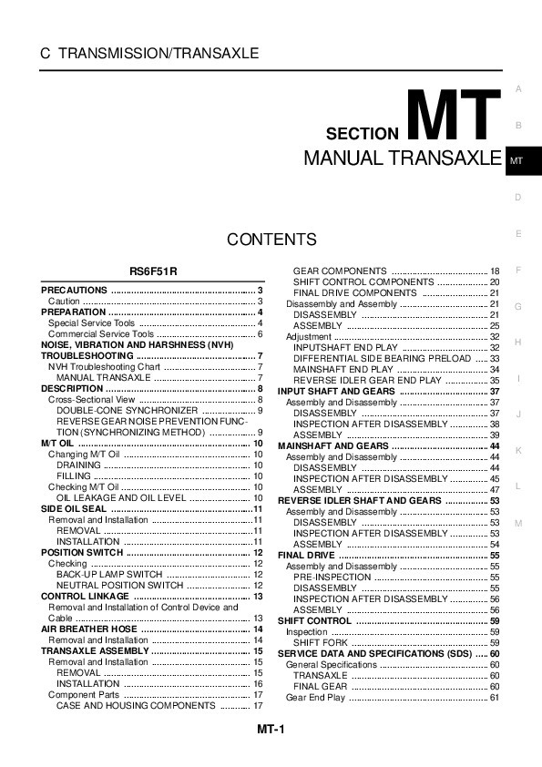
5MT – MANUAL TRANSAXLE MT - 5MT
6MT – MANUAL TRANSAXLE MT - 6MT
AUTOMATIC TRANSAXLE - AT
FRONT & REAR AXLE - AX
FRONT & REAR SUSPENSION - SU
BRAKE SYSTEM - BR
STEERING SYSTEM - ST
RESTRAINT SYSTEM - RS
BODY & TRIM - BT
AUTOMATIC AIR CONDITIONER - ATC
STARTING & CHARGING SYSTEMS - SC
ELECTRICAL SYSTEM - EL
ALPHABETICAL INDEX - IDX
EXCERPT:
Precautions
PRECAUTIONS
I When installing each rubber part, final tightening must be carried out under unladen condition* with tires on ground.
Oil will shorten the life of rubber bushes. Be sure to wipe off any spilled oil.
*: Fuel, radiator coolant and engine oil full. Spare tire, jack, hand tools and mats in designated positions.
I Use flare nut wrench when removing or installing brake tubes.
I After installing removed suspension parts, check wheel alignment.
I Do not jack up at the trailing arm and lateral link.
I Always torque brake lines when installing.
I Lock nuts are unreusable parts; always use new ones.
When replacing, do not wipe the oil off of the new lock nut before tightening.
…
QUICK REFERENCE INDEX
GENERAL INFORMATION GI
MAINTENANCE MA
ALMERA ENGINE MECHANICAL EM
MODEL N15 SERIES ENGINE LUBRICATION &
COOLING SYSTEMS LC
ENGINE CONTROL SYSTEM EC
ACCELERATOR CONTROL,
FUEL & EXHAUST SYSTEMS FE
CLUTCH CL
MANUAL TRANSAXLE MT
AUTOMATIC TRANSAXLE AT
FRONT AXLE & FRONT SUSPENSION FA
REAR AXLE & REAR SUSPENSION RA
BRAKE SYSTEM BR
STEERING SYSTEM ST
RESTRAINT SYSTEM RS
BODY & TRIM BT
HEATER & AIR CONDITIONER HA
ELECTRICAL SYSTEM EL
ALPHABETICAL INDEX IDX
VALVE Oil SEAL
1. Remove rocker cover.
2. Remove camshaft.
3. Remove valve spring. Refer to "CYLINDER HEAD".
4. Remove valve oil seal with a suitable tool.
Piston concerned should be set at TOC to prevent valve from falling.
5. Apply engine oil to new valve oil seal and install it with Tool.
Be Remove the following parts: Engine undercover, Right-side splash cover, Alternator and power steering drive belts, Crankshaft pulley.
Remove front oil seal from front cover. Careful not to damage oil seal portion.
…
Fuel Line Inspection
Make sure that fuel line, fuel filler cap and fuel tank are at- tached correctly. If there is tremble or dir, repair or replace them.
Removal • Installation
WARNING:
When replacing the fuel line part, observe the followings:
Put a “CAUTION: INFLAMMABLE” sign in the workshop.
Be sure to work in a well ventilated area and to furnish workshop with a CO2 fire extinguisher.
Do not smoke while working on the fuel system. Also, work in location without any fire.
WARNING:
Use the following procedure before removing the fuel line parts.
a) Drain engine oil to the anti-explosible container and close it tight.
b) Release fuel pressure from the fuel line. Refer to “FUEL PRESSURE RELEASE” (QG16: EC-26).
c) Disconnect the battery negative cable.
Always replace O-ring with a new one.
Do not install the fuel tube twisted.
Do not tighten the hose clamp excessively. The fuel hose can be damaged.
Make sure that there are no fuel leaks at the fuel system connections while the engine is running after installing the fuel tube.
a) Turn the ignition switch ON (engine not running) and generate the fuel pressure in the fuel line.
Also, make sure that are no fuel leaks at the connec- tions.
b) Start engine, rev it up and make sure there are no fuel leaks at the fuel system connections.
Use only NISSAN Geunuine part when replacing the fuel filler cap.
…
Almera_(N15-16)....2
'95-'00 Almera (N15)....3
1995 Nissan Almera (Model N15 Series) Sedan & Hatchback....3
1996-1997 Supplement....1669
1998 Supplement....2206
1999-2000 Supplement Manual....2776
Body Repair Manual....2902
01n16s-333....2948
at....2949
Indice....2949
GENERAL....2949
PRECAUCIONES....2955
"AIRBAG" y "PRETENSOR DEL CINTURON DE SEGURIDAD" del sistema de seguridad suplementario (SRS)....2955
Precauciones para el sistema de diagnóstico en el vehículo (EURO-OBD) de T/A y motor - Euro-OBD -....2955
Precauciones....2956
Notas para el servicio o precauciones....2957
Esquema de conexiones y diagnóstico deaverías....2958
PREPARACION....2959
Herramientas especiales de servicio....2959
Herramientas comerciales de servicio....2961
FLUIDO DE LA T/A....2963
Comprobación del fluido de la T/A....2963
Cambio del fluido de la T/A....2963
SISTEMA GENERAL....2965
Ubicación de los componentes eléctricos de laT/A....2965
Diagrama de circuito....2966
Vista seccional - Modelos 3AX00, 3AX01,3AX19, 3AX63 y 3AX64....2968
Vista seccional - Modelos 3AX10 y 3AX18....2969
Circuito de control hidráulico....2970
Mecanismo de cambio....2971
Sistema de control....2980
Mecanismo de control....2981
Válvula de control....2986
DIAGNOSTICO DE AVERIAS - INSPECCION BASICA....3032
Comprobación del fluido de la T/A....3032
Prueba de calado....3032
...
TROUBLE DIAGNOSIS - SPECIFICATION VALUE....7520
Description....7520
Testing Condition....7520
Inspection Procedure....7520
Diagnostic Procedure....7521
TROUBLE DIAGNOSIS FOR INTERMITTENT INCIDENT....7524
Description....7524
Diagnostic Procedure....7524
POWER SUPPLY CIRCUIT FOR ECM....7525
Wiring Diagram....7525
Diagnostic Procedure....7526
Component Inspection....7530
ECM RELAY....7530
DTC U1000, U1001 CAN COMMUNICATION LINE....7531
Description....7531
On Board Diagnosis Logic....7531
DTC Confirmation Procedure....7531
Wiring Diagram....7532
Diagnostic Procedure....7533
DTC P0011 IVT CONTROL....7534
Description....7534
SYSTEM DESCRIPTION....7534
CONSULT-II Reference Value in Data Monitor Mode....7534
On Board Diagnosis Logic....7535
FAIL-SAFE MODE....7535
DTC Confirmation Procedure....7535
WITH CONSULT-II....7535
WITH GST....7536
Diagnostic Procedure....7536
DTC P0031, P0032 HO2S1 HEATER....7537
Description....7537
SYSTEM DESCRIPTION....7537
OPERATION....7537
CONSULT-II Reference Value in Data Monitor Mode....7537
On Board Diagnosis Logic....7537
DTC Confirmation Procedure....7537
WITH CONSULT-II....7537
WITH GST....7538
Wiring Diagram....7539
Diagnostic Procedure....7540
Component Inspection....7542
HEATED OXYGEN SENSOR 1 HEATER....7542
Removal and Installation....7542
HEATED OXYGEN SENSOR 1....7542
DTC P0037, P0038 HO2S2 HEATER....7543
Description....7543
SYSTEM DESCRIPTION....7543
OPERATION....7543
CONSULT-II Reference Value in Data Monitor Mode....7543
On Board Diagnosis Logic....7543
DTC Confirmation Procedure....7543
WITH CONSULT-II....7543
WITH GST....7544
Wiring Diagram....7545
Diagnostic Procedure....7546
Component Inspection....7548
HEATED OXYGEN SENSOR 2 HEATER....7548
Removal and Installation....7548
HEATED OXYGEN SENSOR 2....7548
DTC P0102, P0103 MAF SENSOR....7549
Component Description....7549
CONSULT-II Reference Value in Data Monitor Mode....7549
On Board Diagnosis Logic....7549
FAIL-SAFE MODE....7549
DTC Confirmation Procedure....7550
PROCEDURE FOR DTC P0102....7550
With CONSULT-II....7550
With GST....7550
PROCEDURE FOR DTC P0103....7550
With CONSULT-II....7550
With GST....7550
Wiring Diagram....7551
Diagnostic Procedure....7552
Component Inspection....7554
MASS AIR FLOW SENSOR....7554
Removal and Installation....7554
MASS AIR FLOW SENSOR....7554
DTC P0112, P0113 IAT SENSOR....7555
Component Description....7555
On Board Diagnosis Logic....7555
DTC Confirmation Procedure....7555
WITH CONSULT-II....7555
WITH GST....7555
Wiring Diagram....7556
Diagnostic Procedure....7557
Component Inspection....7558
INTAKE AIR TEMPERATURE SENSOR....7558
Removal and Installation....7558
MASS AIR FLOW SENSOR....7558
DTC P0117, P0118 ECT SENSOR....7559
Component Description....7559
On Board Diagnosis Logic....7559
FAIL-SAFE MODE....7559
DTC Confirmation Procedure....7560
WITH CONSULT-II....7560
WITH GST....7560
Wiring Diagram....7561
Diagnostic Procedure....7562
Component Inspection....7563
ENGINE COOLANT TEMPERATURE SENSOR....7563
Removal and Installation....7563
ENGINE COOLANT TEMPERATURE SENSOR....7563
DTC P0132 HO2S1....7564
Component Description....7564
CONSULT-II Reference Value in Data Monitor Mode....7564
On Board Diagnosis Logic....7564
DTC Confirmation Procedure....7565
WITH CONSULT-II....7565
WITH GST....7565
Wiring Diagram....7566
Diagnostic Procedure....7567
Component Inspection....7568
HEATED OXYGEN SENSOR 1....7568
With CONSULT-II....7568
Without CONSULT-II....7569
Removal and Installation....7569
HEATED OXYGEN SENSOR 1....7569
DTC P0133 HO2S1....7570
Component Description....7570
CONSULT-II Reference Value in Data Monitor Mode....7570
On Board Diagnosis Logic....7570
DTC Confirmation Procedure....7571
WITH CONSULT-II....7571
Overall Function Check....7572
WITH GST....7572
Wiring Diagram....7573
Diagnostic Procedure....7574
Component Inspection....7577
HEATED OXYGEN SENSOR 1....7577
With CONSULT-II....7577
Without CONSULT-II....7578
Removal and Installation....7579
HEATED OXYGEN SENSOR 1....7579
DTC P0134 HO2S1....7580
Component Description....7580
CONSULT-II Reference Value in Data Monitor Mode....7580
On Board Diagnosis Logic....7580
DTC Confirmation Procedure....7581
WITH CONSULT-II....7581
Overall Function Check....7581
WITH GST....7581
Wiring Diagram....7583
Diagnostic Procedure....7584
Component Inspection....7585
HEATED OXYGEN SENSOR 1....7585
With CONSULT-II....7585
Without CONSULT-II....7586
Removal and Installation....7586
HEATED OXYGEN SENSOR 1....7586
DTC P0138 HO2S2....7587
Component Description....7587
CONSULT-II Reference Value in Data Monitor Mode....7587
On Board Diagnosis Logic....7587
DTC Confirmation Procedure....7588
WITH CONSULT-II....7588
WITH GST....7588
Wiring Diagram....7589
Diagnostic Procedure....7590
Component Inspection....7591
HEATED OXYGEN SENSOR 2....7591
With CONSULT-II....7591
Without CONSULT-II....7592
Removal and Installation....7592
HEATED OXYGEN SENSOR 2....7592
DTC P0139 HO2S2....7593
Component Description....7593
CONSULT-II Reference Value in Data Monitor Mode....7593
On Board Diagnosis Logic....7593
DTC Confirmation Procedure....7594
WITH CONSULT-II....7594
Procedure for COND1....7594
Procedure for COND2....7595
Procedure for COND3....7595