
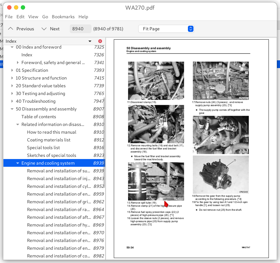
Komatsu WA270-7 WA270-8 Wheel Loader Workshop Repair Service Manual PDF - MKMTSWA270OPES.zip
A full workshop service and repair manual for the Komatsu Wheel Loader WA270, featuring Electrical Wiring Diagrams and every technical detail needed to maintain, troubleshoot, fix, and rebuild the machine just as professional service technicians would.
The Komatsu WA270 Wheel Loader workshop service repair manual contains:
* Numbered table of contents easy to use so that you can find the information you need fast.
* Detailed sub-steps expand on repair procedure information
* Numbered instructions guide you through every repair procedure step by step.
* Troubleshooting and electrical service procedures are combined with detailed wiring diagrams for ease of use.
* Notes, cautions and warnings throughout each chapter pinpoint critical information.
* Bold figure number help you quickly match illustrations with instructions.
* Detailed illustrations, drawings and photos guide you through every procedure.
* Enlarged inset helps you identify and examine parts in detail.
CEBM027600 - Wheel Loader WA270-7 Shop Manual.pdf
CEBM031301 - Wheel Loader WA270-8 Shop Manual.pdf
SEN06255-01 - Wheel Loader WA270-7 Shop Manual.pdf
SEN06255-02 - Wheel Loader WA270-7 Shop Manual.pdf
TEN00617-01 - Wheel Loader WA270-7 Shop Manual.pdf
PRODUCT DETAILS:
Total Pages: 5,443 pages
File Format: PDF (Internal Links, Bookmarked, Table of Contents, Searchable, Printable, high quality)
Language: English
TABLE OF CONTENTS
CEBM027600 - Wheel Loader WA270-7 Shop Manual...1
00 Index and foreword ...3
Index ...4
Foreword, safety and general information ...19
Important safety notice ...19
How to read the shop manual ...26
Explanation of terms for maintenance standard ...28
Handling equipment of fuel system devices ...30
Handling of intake system parts ...31
Handling of hydraulic equipment ...32
Method of disconnecting and connecting of push-pull type coupler ...34
Handling of electrical equipment ...37
How to read electric wire code ...45
Precautions when performing operation ...48
Practical use of KOMTRAX ...53
Standard tightening torque table ...54
List of abbreviation ...60
Conversion table ...65
01 Specification ...71
Table of contents ...72
Specifications ...73
Specification drawing ...73
Specifications ...77
Weight table ...87
Table of fuel, coolant, and lubricants ...91
10 Structure and function ...93
Table of contents ...94
Engine and cooling system ...96
Engine related parts ...96
KVGT ...98
EGR system piping drawing ...105
EGR system circuit diagram ...107
EGR valve ...109
EGR cooler ...111
KCCV layout drawing ...112
KCCV ventilator ...114
KDPF ...116
Cooling system ...120
Cooling fan motor ...122
Power train ...133
Power train system ...133
Layout of power train parts ...135
Damper ...136
HST pump ...137
HST motor1 ...150
HST motor2 ...152
Transfer ...157
Clutch solenoid valve ...164
Drive shaft ...166
Axle ...167
Differential ...169
Torque proportional differential ...173
Limited slip differential ...175
Final drive ...180
Steering system ...183
Layout of steering devices ...183
Steering column ...184
Priority valve ...185
Cushion valve ...189
Emergency steering valve ...190
Orbitrol valve ...193
2way restrictor valve ...199
Brake system ...200
Layout of brake parts ...200
Brake accumulator charge valve ...202
Brake valve ...207
Brake accumulator ...211
Slack adjuster ...212
Brake ...214
Parking brake control ...217
Parking brake ...218
Parking brake solenoid valve ...219
Undercarriage and frame ...221
Axle mount ...221
Center hinge pin ...223
Tire ...224
Hydraulic system ...226
Hydraulic component layout ...226
Work equipment control ...228
Hydraulic tank ...229
Double type gear pump ...232
Steering and work equipment pump ...233
Control valve ...245
CLSS ...255
Hydraulic circuit diagram and names of valves ...259
Self-pressure reducing valve ...272
Work equipment PPC valve ...277
Work equipment lock solenoid valve ...285
PPC circuit accumulator ...286
ECSS accumulator ...287
Work equipment ...288
Work equipment linkage ...288
Bucket ...289
Cab and its attachments ...290
ROPS cab ...290
Cab mount ...292
Electrical system ...293
Engine control system ...293
Preheating system ...296
Engine output limit function ...298
Automatic warm-up function ...299
Parking brake control system ...300
System operating lamp function ...304
Battery disconnect switch function ...305
HST controller system ...307
Machine monitor system ...347
Rearview monitor system ...368
KOMTRAX system ...371
System component parts ...374
Sensor ...397
20 Standard value tables ...417
Table of contents ...418
Standard service value table ...419
Standard value table for engine ...419
Standard value table for machine ...421
Standard value table for electrical system ...433
30 Testing and adjusting ...443
Table of contents ...444
Related information on testing and adjusting ...446
Tools for testing and adjusting ...446
Sketch of tools for testing and adjusting ...452
Engine and cooling system ...453
Testing engine speed ...453
Testing boost pressure ...454
Testing exhaust gas temperature ...456
Testing exhaust gas color ...457
Testing and adjusting valve clearance ...459
Testing compression pressure ...461
Testing blowby pressure ...465
Testing engine oil pressure ...466
Testing EGR valve and KVGT oil pressures ...467
Testing fuel pressure ...468
Testing fuel discharge, return and leakage ...472
Bleeding air from fuel system ...477
Testing fuel circuit for leakage ...479
Handling cylinder cutout mode operation ...480
Handling no-injection cranking operation ...481
Testing of KDPF and muffler stack for looseness and damage ...482
Testing of installed condition of cylinder heads and manifolds ...483
Testing engine piping for damage and looseness ...484
Testing and adjusting air conditioner compressor belt tension ...485
Replacing alternator belt ...486
Power train ...487
Testing oil leakage from axle final drive ...487
Testing drive shaft for looseness, backlash, and damage ...488
Testing accelerator pedal ...489
Testing and adjusting HST oil pressure ...490
Testing transfer clutch control pressure ...493
Steering system ...494
Testing directional lever ...494
Testing steering wheel ...495
Testing work equipment control lever ...497
Testing and adjusting steering circuit oil pressure ...499
Bleeding air from steering cylinder circuit ...501
Brake system ...502
Testing brake pedal ...502
Testing braking performance ...503
Testing and adjusting of accumulator charge pressure ...504
Testing wheel brake oil pressure ...506
Testing lowering of wheel brake pressure ...507
Testing wear of wheel brake disc ...509
Bleeding air from wheel brake circuit ...510
Releasing remaining pressure in brake accumulator circuit ...511
Testing parking brake performance ...512
Testing wear of parking brake disc ...513
Testing parking brake release pressure ...514
Method of releasing parking brake manually ...515
Hydraulic system ...516
Testing cooling fan speed ...516
Testing cooling fan pump circuit oil pressure ...517
Bleeding air from hydraulic fan circuit ...519
Testing and adjusting work equipment PPC oil pressure ...520
Testing and adjusting work equipment oil pressure ...522
Bleeding air from work equipment circuit ...526
Releasing remaining pressure from work equipment circuit ...527
Testing ECSS accumulator nitrogen gas pressure and procedure for charging accumulator with nitrogen gas ...529
Work equipment ...533
Testing and adjusting bucket positioner and bucket proximity switch ...533
Testing and adjusting boom position detection lever ...535
Electrical system ...536
Adjusting replaced, reassembled or added sensor, controller, etc. with machine monitor ...536
Special functions of machine monitor ...537
Adjusting rearview camera angle ...615
Handling voltage circuit of engine controller ...616
Handling battery disconnect switch ...617
Testing diodes ...618
Pm clinic ...619
Pm Clinic service ...619
Check sheet ...620
40 Troubleshooting ...625
Table of contents ...626
Related information on troubleshooting ...635
Troubleshooting points ...635
Sequence of events in troubleshooting ...637
Checks before troubleshooting ...639
Inspection procedure before troubleshooting ...641
Preparation for troubleshooting of electrical system ...658
Classification and procedures for troubleshooting ...664
Symptom and troubleshooting numbers ...667
Information described in troubleshooting table ...670
Procedure for troubleshooting wiring harness of pressure sensor system for open circuit ...672
Connector list and layout ...675
Connector contact identification ...689
T-branch box and T-branch adapter table ...728
Fuse location table ...733
Precautions for KDPF (KCSF and KDOC) Cleaning and Replacement ...736
Precautions when performing troubleshooting of machine monitor ...739
Processing procedure of harness checker for troubleshooting of machine monitor LCD unit ...741
Preparation of dummy temperature sensor (for KDOC and KDPF temperature sensors) ...746
Preparation of short circuit electrical connector (for failure codes [CA1883] and [CA3135]) ...747
Failure codes table ...748
Troubleshooting by failure code (Display of code) ...760
Failure code [2F00MA] Failure of Parking Brake Circuit ...760
Failure code [2F00MB] Malfunction of Parking Brake ...763
Failure code [2G42ZG] Accumulator Oil Pressure Low (Front) ...765
Failure code [2G43ZG] Accumulator Oil Pressure Low (Rear) ...767
Failure code [6091NX] HST Oil Filter Clogging ...769
Failure code [7RHYKA] Disconnection of Fan Variable Control Sol. ...771
Failure code [7RHYKB] Ground Fault of Fan Variable Control Sol. ...773
Failure code [7RHYKY] Hot Short of Fan Variable Control Sol. ...775
Failure code [879AKA] A/C Inner Sensor Open Circuit ...777
Failure code [879AKB] A/C Inner Sensor Short Circuit ...778
Failure code [879BKA] A/C Outer Sensor Open Circuit ...779
Failure code [879BKB] A/C Outer Sensor Short Circuit ...780
Failure code [879CKA] Ventilating Sensor Open Circuit ...781
Failure code [879CKB] Ventilating Sensor Short Circuit ...782
Failure code [879DKZ] Sunlight Sensor Open or Short Circuit ...783
Failure code [879EMC] Ventilation Damper Abnormality ...784
Failure code [879FMC] Air Mix Damper Abnormality ...785
Failure code [989L00] Engine Controller Lock Caution 1 ...786
Failure code [989M00] Engine Controller Lock Caution 2 ...787
Failure code [989N00] Engine Controller Lock Caution 3 ...788
Failure code [A1U0N3] HC Desorb Request 1 ...789
Failure code [A1U0N4] HC Desorb Request 2 ...791
Failure code [AB00KE] Charge Voltage Low ...793
Failure code [AB00KY] Hot Short of Alternator R Terminal ...794
Failure code [B@BAZG] Eng Oil Press Low ...795
Failure code [B@BCNS] Eng Water Overheat ...796
Failure code [B@BCZK] Eng Water Level Low ...797
Failure code [B@CRNS] HST Oil Temp. Overheat ...799
Failure code [CA115] Eng Ne and Bkup Speed Sens Error ...800
Failure code [CA122] Chg Air Press Sensor High Error ...801
Failure code [CA123] Chg Air Press Sensor Low Error ...803
Failure code [CA131] Throttle Sensor High Error ...805
Failure code [CA132] Throttle Sensor Low Error ...807
Failure code [CA144] Coolant Temp Sens High Error ...809
Failure code [CA145] Coolant Temp Sens Low Error ...811
Failure code [CA153] Chg Air Temp Sensor High Error ...813
Failure code [CA154] Chg Air Temp Sensor Low Error ...815
Failure code [CA187] Sensor 2 Supply Volt Low Error ...817
Failure code [CA221] Ambient Press Sensor High Error ...819
Failure code [CA222] Ambient Press Sensor Low Error ...821
Failure code [CA227] Sensor 2 Supply Volt High Error ...823
Failure code [CA234] Eng Overspeed ...824
Failure code [CA238] Ne Speed Sensor Supply Volt Error ...825
Failure code [CA239] Ne Speed Sens Supply Volt High Error ...826
Failure code [CA271] IMV/PCV1 Short Error ...827
Failure code [CA272] IMV/PCV1 Open Error ...829
Failure code [CA295] Ambient Press Sens In Range Error ...831
Failure code [CA322] Inj #1(L#1) Open/Short Error ...832
Failure code [CA323] Inj #5(L#5) Open/Short Error ...834
Failure code [CA324] Inj #3(L#3) Open/Short Error ...836
Failure code [CA325] Inj #6(L#6) Open/Short Error ...838
Failure code [CA331] Inj #2(L#2) Open/Short Error ...840
Failure code [CA332] Inj #4(L#4) Open/Short Error ...842
Failure code [CA343] ECM Critical Internal Failure ...844
Failure code [CA351] Injectors Drive Circuit Error ...845
Failure code [CA352] Sensor 1 Supply Volt Low Error ...846
Failure code [CA356] Mass Air Flow Sensor High Error ...848
Failure code [CA357] Mass Air Flow Sensor Low Error ...850
Failure code [CA386] Sensor 1 Supply Volt High Error ...852
Failure code [CA428] Water in Fuel Sensor High Error ...853
Failure code [CA429] Water in Fuel Sensor Low Error ...855
Failure code [CA431] Idle Validation Sw Error ...857
Failure code [CA432] Idle Validation Process Error ...860
Failure code [CA435] Eng Oil Press Sw Error ...863
Failure code [CA441] Battery Voltage Low Error ...864
Failure code [CA442] Battery Voltage High Error ...866
Failure code [CA449] Rail Press Very High Error ...867
Failure code [CA451] Rail Press Sensor High Error ...868