
New Holland Tractors TL70A, TL80A, TL 90A, TL100 Repair Service Manual - MNHT6035449100.zip & MNHT6035451100.zip
New Holland Tractors TL70A, TL80A, TL 90A, TL100 Repair Service Manual
603.54.491.00 - New Holland Tractors TL70A, TL80A, TL 90A, TL100A Service Manual.pdf
603.54.511.00 - New Holland Tractors TL70A, TL80A, TL 90A, TL100A Service Manual.pdf
Complete service repair manual with Electrical Wiring Diagrams for New Holland Tractors TL70A, TL80A, TL 90A, TL100, with all the technical information to maintain, diagnose, repair, rebuild like professional mechanics.
New Holland Tractors TL70A, TL80A, TL 90A, TL100 workshop service repair manual includes:
* Numbered table of contents easy to use so that you can find the information you need fast.
* Detailed sub-steps expand on repair procedure information
* Numbered instructions guide you through every repair procedure step by step.
* Troubleshooting and electrical service procedures are combined with detailed wiring diagrams for ease of use.
* Notes, cautions and warnings throughout each chapter pinpoint critical information.
* Bold figure number help you quickly match illustrations with instructions.
* Detailed illustrations, drawings and photos guide you through every procedure.
* Enlarged inset helps you identify and examine parts in detail.
PRODUCT DETAILS:
Total Pages: 1,621 + 2,08 pages
File Format: PDF (Internal Links, Bookmarked, Table of Contents, Searchable, Printable, high quality)
Language: English
MAIN SECTIONS
CONTENT...3
SECTION 00 -- GENERAL GUIDELINES...15
SECTION 10 -- ENGINE...21
SECTION 18 -- CLUTCH...151
SECTION 21 -- TRANSMISSIONS...167
SECTION 23 -- DRIVE LINES...293
SECTION 25 -- FRONT AXLE MECHANICAL TRANSMISSION...313
SECTION 27 -- REAR AXLE MECHANICAL TRANSMISSION...365
SECTION 31 -- POWER TAKE--OFF...423
SECTION 33 -- BRAKES...479
SECTION 35 -- HYDRAULIC SYSTEM...519
SECTION 41 -- STEERING...815
SECTION 44 -- AXLES AND WHEELS...853
SECTION 50 -- AUXILIARY UNITS...869
SECTION 55 -- ELECTRICAL SYSTEM...917
SECTION 90 -- BODYWORK AND DRIVING POSITION...2037
TABLE OF CONTENTS
SECTIONS...1
INTRODUCTION...2
IMPORTANT WARNINGS...2
CONTENTS...3
SECTION 00 - GENERAL INSTRUCTIONS...12
IMPORTANT NOTICE...12
SHIMMING...12
ROTATING SHAFT SEALS...12
O RING SEALS...12
SEALING COMPOUNDS...12
BEARINGS...13
SPRING PINS...13
SPARE PARTS...13
TOOLS...13
IMPORTANT NOTES...13
MOVING THE TRACTOR WITH THE BATTERY REMOVED...13
SAFETY REGULATIONS...14
CONSUMABLES...17
SECTION 10 ENGINE...18
Chapter 1 Engine...18
General specifications...19
Data...22
Tightening torques...28
Tools...30
Engine views...31
Lubrication diagram...33
Cooling system diagram...34
Fault diagnosis...38
Engine R.I...42
Engine D.A. Checks, measurements and repairs...62
Crankshaft front seal Replacement...114
Crankshaft rear seal Replacement...117
Valve tappet and rocker arm clearance Adjustment...120
Engine injector R.I...123
Bosch injection pump R.I. Timing. Air bleed...126
Coolant pump R.I...134
Thermostat valve R.I...136
Radiator R.I...138
Coolant pump and generator drive belts. Tension adjustment...144
SECTION 18 CLUTCH...146
Chapter 1 Clutch...146
Clutches. General specifications...147
Tightening Torques...148
Tools...148
Cross sectional views...149
Fault diagnosis...150
Checks, dimensions and repairs...151
Main transmission clutch release Adjustment...153
Clutch R.I...154
Dual Clutch 12 /12 Test bench overhaul and adjustment...157
SECTION 21 TRANSMISSIONS...162
Chapter 1 Transmission and range gear (12 x 4)...162
Transmission and range gear. Data...163
Tightening Torques...164
Tools...165
Cross sectional views...167
Description and Operation...169
Fault diagnosis...169
Chapter 2 Reverser...171
Transmission with range gear and reverser. Data...172
Tightening Torques...173
Tools...174
Cross sectional views...174
Description and Operation...176
Fault diagnosis...176
Clutch reverser casing. Disassembly Assembly...177
Chapter 3 Dual Command (2 Speed Power Shift)...183
Data...184
Tightening Torques...186
Tools...187
Cross sectional views...188
Description and Operation...192
Fault diagnosis...198
Clutch casing with Dual Command (2 Speed Power Shift) R.I...200
Clutch casing with Dual Command (2 Speed Power Shift) D.A...209
Dual Command (2 Speed Power Shift) linkage adjustment...218
Dual Command (2 Speed Power Shift) solenoid valve R.I...219
Dual Command (2 Speed Power Shift) control valve R...223
Dual Command (2 Speed Power Shift) control valve D.A...227
Chapter 4 Reverser and creeper unit...230
Data...231
Tightening Torques...232
Tools...233
Cross sectional views...235
Description and Operation...237
Fault diagnosis...237
Reverser clutch casing and creeper unit D.A...238
Chapter 5 Power Shuttle transmission with Dual Command...245
Data...246
Tightening Torques...248
Tools...250
Cross sectional views...252
Description and Operation...255
Clutch casing with Power Shuttle and Dual Command (2 Speed Power Shift) units D.A...262
Clutch (a) D.A...269
Clutch (B) D.A...274
SECTION 23 DRIVE LINES...275
Chapter 1 Drive lines...275
Data...276
Tightening Torques...277
Tools...277
Cross sectional views...278
Description of operation and hydraulic diagrams...279
Fault diagnosis...280
Services control valve R.I...281
Services control valve D.A...284
Drive gear housing R.I...286
Drive gear housing D.A...291
SECTION 25 FRONT AXLE MECHANICAL TRANSMISSION...295
Chapter 1 Front axle mechanical transmission...295
Data...296
Tightening Torques...298
Tools...300
Cross sectional views...303
Rules for correctly fitting the axle support to the engine...307
Description of LIM SLIP self locking differential operation...309
Description of front differential lock operation...310
Fault diagnosis...311
Front axle R.I...312
Front axle D.A. Overhaul...316
Front axle differential with LIM SLIP unit Overhaul...325
Front axle differential with LIM SLIP unit Overhaul...326
Differential lock clutch assembly Overhaul...328
Front epicyclic final drive without brake D.A...330
Front epicyclic final drive with brake D.A...334
Steering knuckle pins and bearings...337
Adjustments...338
SECTION 27 REAR AXLE MECHANICAL TRANSMISSION...347
Chapter 1 Rear axle mechanical transmission...347
Data...348
Tightening Torques...349
Tools...351
Cross sectional views...356
Description and Operation...361
Fault diagnosis...362
Gearbox transmission casing R.I...364
Gearbox/transmission casing D.A. and adjustments...378
Adjustments differential lock control pedal travel...397
Final drive casing R.I...398
Epicyclic final drive D.A...401
Drive wheel shaft D.A...402
SECTION 31 POWER TAKE OFF...404
Chapter 1 Mechanical power take off...404
Data...405
Tools...408
Tightening Torques...409
Cross sectional views...410
Description of operation...413
Fault diagnosis...414
Power take off housing R.I...415
Power take off driving shaft D.A...418
Driven shaft and other parts D.A...418
Chapter 2 Electro hydraulic power take off...421
Data...422
Tools...425
Tightening Torques...426
Cross sectional views...427
Description, operation and hydraulic diagrams...433
Fault diagnosis...444
Power take off clutch brake Replacement...445
Electro hydraulic power take off housing R.I...447
Speed selection control device D.A...451
Power take off driving shaft D.A...451
PTO driven shaft D.A...451
SECTION 33 BRAKES...458
Chapter 1 Brakes...458
Data...458
Tightening Torques...459
Cross sectional views...460
Description and Operation...461
Fault diagnosis...464
Handbrake control. Travel adjustment...465
Parking brake casing. R.I...466
Parking brake casing. D.A...466
Brake hydraulic system. Air bleed...469
Service brake pump. R.I...470
Service brake cylinder. R.I...472
SECTION 35 HYDRAULIC SYSTEMS...477
Chapter 1 Rear mechanical hydraulic lift...477
Data...478
Tightening Torques...483
Tools...485
Cross sectional views...486
Description and Operation...488
Fault diagnosis...492
Rear lift oil pump D.A...495
Lift O Matic control D.A...496
Rear lift linkage adjustments...497
Rear lift external controls D.A. and adjustments...500
Rear lift R.I...501
Rear hydraulic lift internal controls D.A. and adjustments...508
Arm shaft and lifting cylinder D.A...508
Lift shaft bushings Replacement...508
Lift control valve R.I...519
Lift control valve D.A...521
Lift pressure relief valve R.I...526
Lift pressure relief valve Setting...526
Chapter 2 Open centre system auxiliary control valves...527
Data Tools...527
Tightening Torques...528
Cross sectional views...529
Description and Operation...532
Troubleshooting...492
Auxiliary control valves D.A...536
Flow control valve D.A...539
Chapter 3 Auxiliary control valves for remote control (BOSCH)...542
Data...543
Tools...543
Tightening Torques...544
Description and Operation...545
Auxiliary control valve components...547
Control valve inter connection...551
Lifting oil flow (Cylinder extension)...552
Lowering oil flow (Cylinder retraction)...554
Neutral oil flow...555
Float mode oil flow...556
Automatic release pressure regulating valve operation...557
Operation of two or more control valves simultaneously...558
Auxiliary control valves R.I...560
Auxiliary control valves. D.A...563
Chapter 4 Trailer brake auxiliary control valves...568
Cross sectional views...568
Description and Operation...568
Trailer brakes control valve hydraulic circuit diagram with KONTAK control valves...569
Trailer brake control valve hydraulic circuit diagram with BOSCH control valves...570
Functional testing and troubleshooting...577
Chapter 5 Supplementary cylinder...580
Data...580
Cross sectional views...580
Description and Operation...580
Supplementary cylinder R.I...581
Supplementary cylinder D.A...581
Chapter 6 Electronic draft control...582
Data...583
Tightening Torques...585
Tools...585
Details of electronic lift components...586
Description and Operation...589
Lift electronic control centre Replacement...593
Electronic lift control panel R.I...594
Lift arm potentiometer Replacement...595
Draft sensor R.I...596
Electronic lift calibration...598
Electronic draft control R.I...600
Hydraulic control valve R. I...606
Chapter 7 Ventral control valves for Walvoil type open centre system...608
Ventral control valve specifications...608
Tightening torques...609
Ventral control valve diagrams...610
Ventral control valve joystick...612
Control valve circuit...615
Hydraulic diagram...616
Description and operation of ventral control valve...617
Chapter 8 Front Loader...626
Features...627
Maximum permissible front axle weights...628
Tightening torques...629
Diagrams...630
Ventral control valve specifications...633
Ventral control valve joystick...635
Switching full / dipped beam headlights on lights fitted on handrails...638
Ballasting the tractor for front loader operation...642
Loader general description...643
Loader installation removal...653
Attachment installation removal...658
Lift arm types and functions...662
Smooth ride control ...671
Multi Quick coupler connection disconnection...674
Hydraulic functions and flow diagram of loaders...686
Hydraulic flow diagrams...697
Repair instructions...714
Hydraulic components...720
Fault finding...725
SECTION 41 STEERING...731
Chapter 1 Steering...731
Data...732
Tightening Torques...735
Components and operating diagrams...736
Fault diagnosis...741
Tools...742
Hydrostatic steering control valve R.I...743
Hydrostatic steering control valve D.A...748
Hydrostatic steering control valve bench tests...762
Hydrostatic steering oil pump D.A...765
Front axle steering cylinder R.I...766
Front axle steering cylinder R.I...767
SECTION 44 AXLES AND WHEELS...768
Chapter 1 Axles and wheels...768
Data...768
Cross sectional views...770
Tightening Torques...771
Fault diagnosis and equipment...772
Front axle hub D. A...773
Front axle R.I...776
Stub axle Overhaul...779
Checking 2 WD front wheel camber and toe in...782
Checking 4 WD front wheel alignment...783
SECTION 50 AUXILIARY UNITS...784
Chapter 1 Auxiliary units...784
Safety regulations...785
General specifications...786
Tools...787
Operating principles...788
Main components of the cab air conditioning system...790
Warnings for air conditioning system repair operations...794
Cab controls...795
Instructions for use air conditioning system...798
Refrigerant recovery recycling and evacuation charging stations...798
Electronic leak detector 380000314...799
Air conditioning system maintenance...800
Air conditioning system troubleshooting...801
Air conditioning system troubleshooting...802
Cab air conditioning system functional testing...806
Checking for gas leaks with leak detector 380000314...807
Compressor drive belts. Tension adjustment...808
Air conditioner compressor. R.I...810
Heating pipes. Replacement...813
Air conditioning pipes. Replacement...815
Air conditioner condenser. Replacement...821
Dryer filter. Replacement...822
Cab heater unit. R.I...824
Air conditioner evaporator. Replacement...827
Electric cab fan. R.I...830
SECTION 55 ELECTRICAL SYSTEM...832
Chapter 1 INSTRUMENTS...832
Control panel...833
Analog/Digital Instruments...835
Instruments...835
Liquid crystal displays...836
Central display...837
Using the advanced keypad...841
Transmitters, sensors, switches...843
Maintenance...851
Chapter 2 COMPONENTS...852
Introduction...852
Description of components...853
Advanced Keypad...857
Controls on right hand mudguard...860
Cab controls...862
Controls on right hand cab upright...864
Maintenance...866
Chapter 3 STARTING SYSTEM...868
Technical data...868
Tightening torques...868
Description and operation...869
Troubleshooting...871
System testing...872
Removal Installation...874
Bench tests...877
Chapter 4 CHARGING SYSTEM...879
Technical data...879
Tightening torques...879
Description and Operation...880
Chapter 5 BATTERY...897
Technical data...897
Description and operation...897
Removal Installation...898
Battery checking and maintenance...900
Tests...902
Chapter 6 ELECTRICAL CIRCUITS...905
Electrical circuit components...907
Fuses and relays (version with cab)...912
Maxi fuse box (version with cab)...917
Fuse and relay layout (North America version without cab ...920
Fuse and relay layout (ISO version without cab ...922
Fuse and relay layout (North America version without cab ...924
Maxi fuse box (ISO North America version without cab)...926
Power sockets...927
Operator safety circuit...928
Grid heater relay...929
Grid heater control module...929
Electronic flasher module...929
Ground location points...930
Symbols used in electrical circuits...932
Electric wire colour code...933
Electrical circuits...934
Wiring DIAGRAMS A A/1...935
Starter and recharging circuit DIAGRAM A/1...944
Battery cut out circuit DIAGRAM B...950
Wiring DIAGRAM C...957
Wiring DIAGRAMS D E...967
Wiring DIAGRAM F...983
Wiring DIAGRAMS G H...993
Wiring DIAGRAMS I L M...1007
Wiring DIAGRAMS N/1 N/2 O/1 O/2...1027
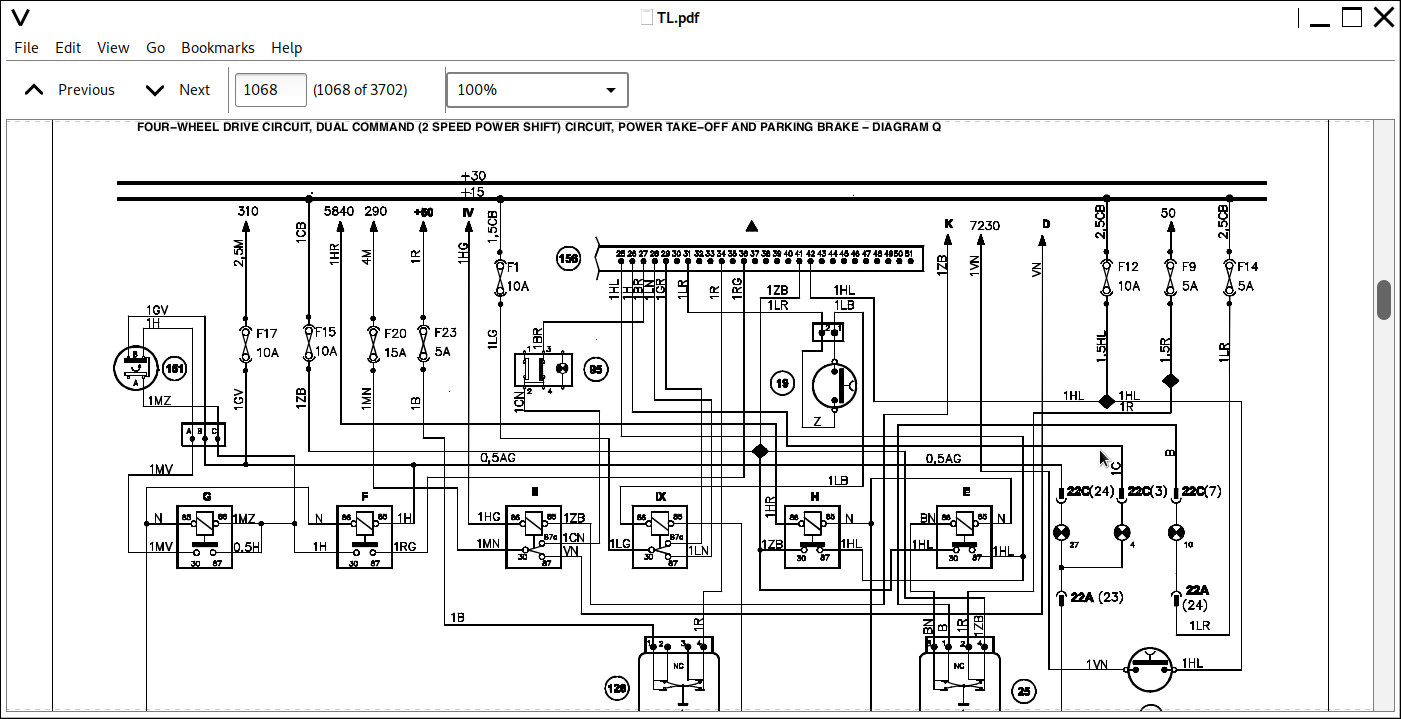
Wiring DIAGRAMS P Q R/1 R/2...1057
Wiring DIAGRAM S...1083
Wiring DIAGRAM T...1095
Electronic transmission control unit input/output circuit (TCM) DIAGRAM U...1104
Measuring device control unit input/output circuit (ADIC) DIAGRAM V...1106
Electronic rear lift control unit input/output circuit DIAGRAM W...1108
Measuring device (ADIC) and transmission control unit (TCM) connection diagram ...1110
Chapter 7 Components Testing...1112
Low transmission oil pressure switch Brake fluid level switch Air filter clogged switch Differential lock indicator switch Lift status switch...1113
Italia version trailer brake valve pressure switches Brake light switch Engine coolant temperature sensor Fuel sediment filter switch ...1115
Handbrake status switch Dual Command (2 Speed Power Shift) switch Gear/Range lever position sensors...1117
Engine oil pressure sensor Switch and clutch pedal potentiometer Speed sensors Clutch pressure switches A and B and oil temperature sensor Alternator ...1120
Radar 4WD pressure switch Fuel level indicator Power Shuttle lever...1124
Electronic lift arm position potentiometer Seat safety switch Draft pin sensors PTO speed sensor ...1126
Front windscreen wiper motor. R.I...1128
Chapter 8 Fault Codes...1129
Introduction...1130
Special Tools...1131
Wiring Harness Repairs...1131
Digital Multi Meter Basic Operation...1134
Electrical Test Procedures...1137
Circuit Components Basic Description...1140
Controller Area Network (CAN) System...1150
Fault Code Displays...1151
H Menu Diagnostic Mode...1153
Fault Code Lists...1154
Calibration U Codes...1161
2001 3000 (Transmission)...1165
5001 6000 (Rear Power Take Off)...1367
6001 7000 (Four Wheel Drive)...1385
7001 8000 (Differential Lock)...1395
14001 15000 (Analog Digital Instrument Cluster)...1409
Electronic Draft Control (EDC)...1477
Chapter 9 HH MENU AND CALIBRATIONS...1553
HH MENU access...1554
HH MENU of the control panel...1556
HH MENU of the transmission...1563
HH MENU of the advanced keypad...1576
SECTION 90 BODYWORK AND DRIVING POSITION...1578
Chapter 1 Removal of components...1578
Platform. R.I...1579
Bonnet. R.I...1587
Driver s seat. R.I...1589
Cabt. R.I...1590
Cab right or left hand door. R.I...1603
Cab windscreen. Repl...1604
Cab RH or LH bottom front window. Repl...1604
Cab rear window. Repl...1606
Left hand upright strip. Repl...1609
Right hand upright strip. Repl...1610
Fixed padding on right hand wall. Repl...1612
Fixed padding on left hand wall. Repl...1615
Hydraulic control lever guard. Repl...1617
Cab ceiling trim. Repl...1619