
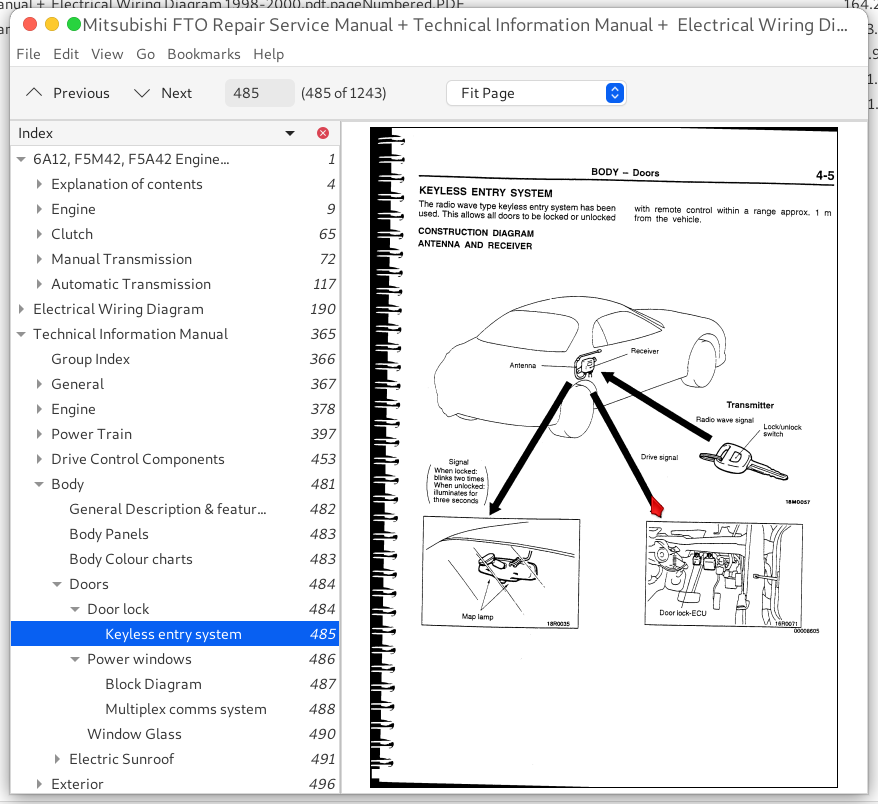
Mitsubishi FTO 1998-2000 Workshop Repair Manual, Wiring Diagram & Technical Information PDF, 6A12 F5M42 F5A42 - MMTBSFTO98OPES.zip
This is the full factory-style service and repair guide for the Mitsubishi FTO, complete with Electrical Wiring Diagrams, containing every technical detail needed to service, troubleshoot, fix, and rebuild the car just like a trained technician.
The Mitsubishi FTO 1998-2000 workshop service repair manual contains:
* Numbered table of contents easy to use so that you can find the information you need fast.
* Detailed sub-steps expand on repair procedure information
* Numbered instructions guide you through every repair procedure step by step.
* Troubleshooting and electrical service procedures are combined with detailed wiring diagrams for ease of use.
* Notes, cautions and warnings throughout each chapter pinpoint critical information.
* Bold figure number help you quickly match illustrations with instructions.
* Detailed illustrations, drawings and photos guide you through every procedure.
* Enlarged inset helps you identify and examine parts in detail.
Mitsubishi FTO 1998-2000 Workshop Manual.pdf
Mitsubishi FTO 1998-2000 Electrical Wiring Diagram.pdf
Mitsubishi 6A12, F5M42, F5A42 Engine & Transmission.pdf
Mitsubishi FTO 1998-2000 Technical Information Manual.pdf
PRODUCT DETAILS:
Total Pages: 1,243 pages
File Format: PDF (Internal Links, Bookmarked, Table of Contents, Searchable, Printable, high quality)
Language: English
TABLE OF CONTENTS
6A12, F5M42, F5A42 Engine & Transmission..1
Explanation of contents..4
Engine & transmission models..6
Standard Parts Tightening Torque table..7
Form-in-place Gaskets (FIPG)..8
Engine..9
General Information..10
Specifications..11
Rework Dimensions..13
Torque Specification..13
Sealants..16
Special Tools..17
Alternator Drive Belt..21
Timing Belt..22
Removal..23
Installation..24
Inspection..25
Auto Tensioner..26
Fuel and Emission Control..27
Installation and service points..28
Ignition system..29
Water Pump and Water Pipe..30
Installation Service Points..31
Intake manifold & exhaust manifold..33
Rocker cover and camshaft..34
Installation & service points..35
Valve clearance adjustment..38
Rocker arm and rocker shaft cap..40
Installation service points..41
Cylinder head and Valves..42
Removal service points..43
Installation service points..44
Inspection..46
Valves..46
Oil pump case and Oil Pan..49
Removal & installation service points..50
Piston and Connecting Rod..53
Removal service points..54
Installation service points..55
Oil Ring installation..56
Piston Rings..56
Connecting Rods..57
Inspection..58
Crankshaft, Cylinder Block, Flywheel and Drive Plate..60
Installation service points..61
Drive plate bolt / flywheel bolt installation..63
Inspection..63
Clutch..65
Specifications..66
Service Specifications..66
Torque Specifications..66
Lubricants..66
Removal and Installation..67
Service points..68
Clutch Release Bearing installation..68
Clutch disc, release bearing and release fork..69
Clutch Release Cylinder..70
Disassembly..70
Re-assembly..71
Inspection..71
Manual Transmission..72
General Information..73
Specifications..74
Gear Ratio Table..74
Service Specifications..74
Sealants & Adhesives..74
Lubricants..75
Snap Rings, Spacers & Thrust Plate..75
Torque Specifications..77
Special tools..78
Disassembly & Re-assembly..81
Service points..84
Input Shaft..89
Service points (dis & re-assembly)..90
Output Shaft..95
Service points (dis & re-assembly)..96
Reverse Idler Gear..103
Speedometer Gear..104
Select Lever..105
Control Housing..106
Disassembly..107
Clutch Housing..109
Transmission Case..112
Differential..114
Dis & re-assembly service points..115
Automatic Transmission..117
General Information..118
Sectional View..119
Specifications..120
Service Specifications..121
Valve Body Spring ID table..121
Snap Ring, Spacer, Thrust Washer, Thrust Race and Pressure plate for adjustment..122
Torque Specifications..126
Sealants..127
Special Tools..127
Disassembly and Re-assembly..130
Disassembly..130
Re-asembly..143
Identification of Thrust Bearings, Thrust races & thrust washers..148
Oil Pump..163
Underdrive Clutch and Input Shaft..164
Reverse Clutch and Overdrive Clutch..166
Direct Clutch dis&re-assembly..169
Direct Planetary Carrier..171
Overdrive Planetary Carrier..174
Low-Reverse Brake..175
Second Brake..176
Transfer Drive Gear..177
Differential..179
Valve Body..182
Speedometer Gear..185
Drive Shaft Oil Seal..186
Reduction Brake Piston..188
Electrical Wiring Diagram..190
FTO Electrical Wiring Foreword..191
How to read the Wiring Diagram..193
Wire Colour Codes..201
Wiring Harness Configuration Diagrams..205
Single Part Installation Position..221
Circuit Diagram..233
Junction Block (J/B)..236
Joint Connector (J/C)..238
Centralized Junction..241
Technical Information Manual..365
Group Index..366
General..367
How to use this manual..368
Model Indications..368
Engine..378
General Information..379
Cooling System..380
Intake & Exhaust..381
Fuel System..382
Control System..383
System Configuration Diagram..384
Idle Speed Control..384
System Configuration Diagram..384
Ignition Timing and Distribution Control..385
System Configuration Diagram..385
Etc..385
Fan Motor Relay Control..386
Self Diagnosis System..386
Emission Control System..387
Engine Mounts..388
Traction Control System..389
System Configuration Diagram..390
Major Component Listing..391
Construction and Operation..392
TCL Control Modes..392
Control System..392
TCL Unit and Diags..393
Accelerator System..396
Power Train..397
Clutch..398
Manual Transmission..399
Sectional View..400
Transmission Case..401
Power Flow..401
Synchroniser..404
Gearshift Control..406
Clutch Control..407
Speedometer Gear..407
Transmission Control..408
Automatic Transmission..409
Sectional View..410
Transmission..411
Torque Convertor..412
Transmission Case..413
Clutches..414
Brake..415
Transfer & Planet gears..417
Powerflow..418
2nd Gear & 3rd Gear..419
4th Gear & 5th Gear..420
Reverse gear..421
Park & Neutral..422
Manual control system..422
Manual control lever..422
Parking mechanism..423
Speedometer Gear..423
Hydraulic Control System..424
Oil Pump & Valve body operation..425
Failsafe operation..433
Oil Filter..436
Sensors & Actuators..437
Comms between ECUs..438
Control Unit..439
Outline of control..440
INVECS-II and learning control..441
Failsafe/Foolproof & diags..445
Self Diagnosis..446
Data List..448
Actuator Test..449
Transmission Control..450
Construction & Operation..450
Front Axle..451
Specifications & construction..451
Rear Axle..452
Drive Control Components..453
Suspension..454
Features..454
Front Suspension..455
Specifications..456
Rear Suspension..457
Specifications..457
Wheel & Tyre..458
Power Steering..458
Specifications..458
Construction diagram..459
Steering Wheel & Column..460
Steering Shaft & Column..461
Shock Absorbing mechanism..461
Oil Pump..462
Brakes..463
Features..463
Construction..463
Specifications..464
Master Cylinder..465
Brake Booster..465
Disc Brakes..466
ABS System..467
Construction..467
Major components & function..467
Schematic Diagram..468
ABS Electrical circuit diagram..469
ABS Fluid Pressure diagram..470
Construction & operation..471
Sensor..471
Stop Lamp switch..471
Actuator..471
Hydraulic unit..471
ABS Motor relay..472
ABS Valve relay..472
ABS Warning lamp..472
ABS ECU..473
Block Diagram..473
Functions of each circuit..473
Brake fluid pressure control..474
Initial check function..475
ABS Valve Relay control..476
ABS Motor relay control..476
Self diagnosis of wheel speed sensor system..476
MUTII Procedure..476
Diagnosis codes..477
Parking Brakes..480
Body..481
General Description & features..482
Body Panels..483
Body Colour charts..483
Doors..484
Door lock..484
Keyless entry system..485
Power windows..486
Block Diagram..487
Multiplex comms system..488
Window Glass..490
Electric Sunroof..491
Construcion..491
ECU Operation & Logic..492
Tilt down..493
Sliding open..493
Sliding closed..494
Key off function..494
Exterior..496
General description & features..497
Bumper..498
Aero parts..498
Outside Mirror..499
Interior..500
General Description & features..501
Instrument panel & floor console..502
Seats..503
Seat belts..504
Rear view mirror..504
Interior trim..505
Boot trim..505
SRS Air bags..506
SRS Schematic..507
Caution label locations..508
'G' force sensor..509
Equipment..510