
John Deere 678 Hay and Forage Wrapping Baler Repair & Diagnostic Manual (TM3301) PDF - MJODTM3301.zip
A full factory service manual featuring electrical wiring schematics for the John Deere 678 Hay and Forage Wrapping Baler, packed with dealer-level workshop data for servicing, troubleshooting, and repairing the machine to a professional standard.
The John Deere 678 Hay and Forage Wrapping Baler workshop Diagnostic and Repair manual contains:
* Numbered table of contents easy to use so that you can find the information you need fast.
* Detailed sub-steps expand on repair procedure information
* Numbered instructions guide you through every repair procedure step by step.
* Troubleshooting and electrical service procedures are combined with detailed wiring diagrams for ease of use.
* Notes, cautions and warnings throughout each chapter pinpoint critical information.
* Bold figure number help you quickly match illustrations with instructions.
* Detailed illustrations, drawings and photos guide you through every procedure.
* Enlarged inset helps you identify and examine parts in detail.
TM3301 - John Deere 678 Hay and Forage Wrapping Baler All Inclusive Technical Manual (Diagnosis and Repair).PDF
Total Pages: 2,271 pages
File Format: PDF (bookmarked, ToC, Searchable, Printable, high quality)
Language: English
MAIN SECTIONS
Electrical System - Repair
Connectors
Sensors and Switches
Actuators
BaleTrak Plus Monitor
Power Train
Walterscheid Powerline
Cam-Type Cut Out Clutch
MaxiCut Precutter Gear Case
Chain Tension
Sprocket Alignment
Braking System - Repair
Hydraulic System - Repair
Bale Density Control Valve
Wrapping Valve
Main Control Valve
Hydraulic Cylinders
Hydraulic Brake
Hydraulic Motor Series
OMP Hydraulic Motor Series
OMS Hydraulic Motor Series
MaxiCut Precutter Electro-Hydraulic Valve
Coupler
Hydraulic System - Adjustment
Miscellaneous
Wheel, Hub and Axle
Bale Shape Indicator
Tongue
Body Frame
Lubrication System - Repair
Drive Chain Lubrication
Automatic Greasing System (S.N. 089000-)
Pickup Repair
MaxiCut Precutter System
Bale Chamber Rolls
Net Tying
Twine Tying
Wrapping Table
Table Drive
Belt and Roll
Wrapping Device
Rubber Mat
Bale Tilt
Wrapping Arm
Diagnostic Trouble Codes
Troubleshooting
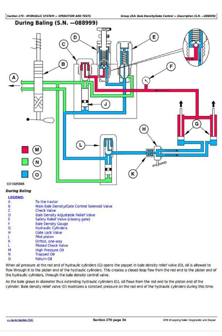
Bale Density/Gate Control
Wrapper Control
Electrical System
General Information
Test Equipment
Electrical System / Diagrams /Diagnostic
- Diagrams for Road Light
- BaleTrak Control
-GreenStar Control
Fuse Diagnosis
Checking Lamp E101 (Optional)
Checking Safety Arm Sensor S103 and Stop Button S101
Checking Torn Film Sensor S104
Checking Wrapping Arm Position Sensor S105, S106
Checking Net Feeding Sensor S107
Checking Gate Open Sensor S108
Checking Gate Closed Sensor S109
Checking Bale On Table Sensor S110
Checking Wrapping Table Position Sensors S111 and S112
Checking Table Positioning Sensor S113
Checking Twine Tying Sensor S114 and Net Cut Sensor S4
Checking Slow Speed Table Belt solenoid valve Y101 (Optional)
Checking solenoid valve Y102 for Lowering Knives
Checking solenoid valve Y103 for Raising Knives
Checking Close Gate solenoid valve Y104, Y105
Checking Table Forward Movement solenoid valve Y106
Checking Table Backward Movement solenoid valve Y107
Checking Fast Speed Arm Rotation solenoid valve Y108
Checking Reverse/Regular Arm Rotation solenoid valve Y109/Y110
Checking Slow Speed Table Movement solenoid valve Y111 and Buzzer H101
Electrical System/Virtual Terminal Control
Electrical Diagrams/Virtual Terminal Control
Diagnostic Mode/Virtual Terminal Control
Machine Setup/Virtual Terminal Control
Software/Virtual Terminal Control
Lubrication System - Operation and Tests
Air Brake System - Operation and Tests
Hydraulic Brake System - Operation and Tests
Hydraulic System - Operation and Tests
Net Tying - Operation and Tests
Twine Tying - Operation and Tests
Special Tools - Dealer-Fabricated
tm3301 - 678 Wrapping Baler
Table of Contents
Foreword
Section 05: Safety
Group 05: Safety Information
Prepare for Emergencies
Service Machine Safely
Avoid High-Pressure Fluids
Support Machine Properly
Wear Protective Clothing
Stay Clear of Rotating Drivelines
Service Machines Safely
Work in Clean Area
Remove Paint Before Welding or Heating
Avoid Heating Near Pressurized Fluid Lines
Illuminate Work Area Safely
Replace Safety Signs
Use Proper Lifting Equipment
Service Tires Safely
Practice Safe Maintenance
Use Proper Tools
Dispose of Waste Properly
Live With Safety
Safety Information - Air Brake System
Section 10: General
Group 05: Baler Serial Numbers
Wrapping Baler Identification Number
Serial Number Plate Description
Historical Account
Group 10: GreenStar Component Identification
Identification Labels
GREENSTAR GREENSTAR is a trademark of Deere & Company Display
GREENSTAR GREENSTAR is a trademark of Deere & Company Mobile Processor
GREENSTAR GREENSTAR is a trademark of Deere & Company KeyCard
GREENSTAR GREENSTAR is a trademark of Deere & Company PC Data Storage Card
GREENSTAR GREENSTAR is a trademark of Deere & Company Controller
Group 15: Torques for Hardware
Metric Bolt and Screw Torque Values
Group 20: Lubrication
Gear Oil
Grease
Grease for Automatic Greasing System
Multiluber Chain Oil
Section 40: Electrical System — Repair
Group 05: Connectors
Special or Essential Tools
Electrical Connector Handling
Disconnecting Electrical Circuit
Insulated and Non-Insulated Connectors
Replace DEUTSCH DEUTSCH is a trademark of the Deutsch Co. Connectors
Install DEUTSCH DEUTSCH is a trademark of the Deutsch Co. Contact
Replace WEATHER PACK WEATHER PACK is a trademark of Packard Electric. Connector
WEATHER PACK WEATHER PACK is a trademark of Packard Electric. Male and Female Connectors
Connectors for Electronic Control Units
Harness Repair (Splice Broken or Cut Wire)
Harness Repair—Splice Connector
Group 10: Sensors and Switches
Sensors and Switches - Summary of References
Sensors and Switches - Specifications
BaleTrak BaleTrak is a trademark of Deere & Company Component Location (S.N. —088999)
GreenStar GreenStar is a trademark of Deere & Company Component Identification (S.N. —088999)
Virtual Terminal Component Identification (S.N. 089000—)
Adjust Oversize-Gate Switch S1 and Full-Size Bale Switch S3 (S.N. —078999)
Adjust Oversize-Gate Switch S1 and Full-Size Bale Switch S3 (S.N. 080000—)
Adjust Net Cut Switch S4 (S.N. —079999)
Adjust Net Cut Sensor S4 (S.N. 080000—)
Adjust Net Cut Sensor S4 for GreenStar Monitor (S.N. 080000—088999)
Adjust Baler Rotation Speed Sensor S6
Adjust Twine Pulley Sensors S7 and S8
Adjust MaxiCut MaxiCut is a trademark of Deere & Company Precutter Reverse Sensor S9
Adjust MaxiCut MaxiCut is a trademark of Deere & Company Precutter Knife Switches S10 and S11
Adjust Safety Arm Sensor S103
Adjust Main Film Sensor S104 (S.N. —039999)
Adjust Main Film Sensor S104 (S.N. 040000—)
Adjust Film Sensors L1 and L2 (S.N. 040000—)
Adjust Wrapping Arm Sensors S105 and S106
Adjust Net Feeding Sensor S107 (S.N. —079999)
Adjust Net Feeding Sensor S107 for GreenStar Monitor (S.N. 080000—088999)
Adjust Gate Position Sensors S108 and S109 (S.N. —088999)
Adjust Gate Opened Sensor S108 (S.N. 089000—)
Adjust Bale on Wrapping Table Sensor S110
Adjust Wrapping Table Position Sensors S111 and S112
Adjust Table Positioning Sensor S113 (S.N. —068999)
Adjust Table Positioning Sensor S113 (S.N. 070000—)
Adjust Twine Pulley Sensor S114 (S.N. —088999)
Group 15: Actuators
Other Material
Actuators - Specifications
Component Identification
Remove and Install Twine Arm Actuator M1
Remove and Install Net Arm Actuator M1 (S.N. 089000—)
Disassemble/Assemble Tying Actuator M1/M2
Group 50: BaleTrak Plus Monitor (S.N. —088999)
BaleTrak Plus Monitor (S.N. —088999) - Specifications
Replace BaleTrak EPROM
Disassembling BaleTrak Monitor
Assembling BaleTrak Monitor
Reprogramming BaleTrak Software
Section 50: Power Train
Group 10: Walterscheid Powerline
Specifications
Exploded-view of Powerline (S.N. —050996)
Exploded-view of Powerline (S.N. 050997—068999)
Exploded-view of Powerline (S.N. 070000— )
Repair Powerline
Group 20: Cam-Type Cut Out Clutch
Cam-Type Cut Out Clutch — Summary of References
Group 20A: Cam-Type Cut Out Clutch (S.N. —061888)
Other Material — Cam-Type Cut Out Clutch (S.N. —061888)
Specifications — Cam-Type Cut Out Clutch (S.N. —061888)
Disassembling Cam-Type Cut Out Clutch
Adjusting Cam-Type Cut Out Clutch
Exploded View of Cam-Type Cut Out Clutch (S.N. —061888)
Assembling Cam-Type Cut Out Clutch — Cam-Type Cut Out Clutch (S.N. —061888)
Group 20B: Cam-Type Cut Out Clutch (S.N.061889—)
Other Material — Cam-Type Cut Out Clutch (S.N.061889—)
Specifications — Cam-Type Cut Out Clutch (S.N.061889—)
Disassemble Cam-Type Cut Out Clutch
Adjust Cam-Type Cut Out Clutch
Exploded View of Cam-Type Cut Out Clutch
Assembling Cam-Type Cut Out Clutch
Group 30: MaxiCut Precutter Gear Case
MaxiCut Precutter Gear Case - Other Material
MaxiCut Precutter Gear Case - Specifications
Removing Gear Case
Exploded View of MAXICUT MAXICUT is a trademark of Deere & Company Precutter Gear Case
Disassembling Gear Case
Inspect Gear Case
Assemble Gear Case
Install Gear Case
Group 35: Chain Tension
Chain Tension - Specifications
Adjusting Roll Drive Chains
Adjust MaxiCut MaxiCut is a trademark of Deere & Company Precutter Pickup Drive Chains
Adjusting MAXICUT MAXICUT is a trademark of Deere & Company Precutter Main Drive Chain
Adjust Wrapping Table Roll Drive Chain
Adjust Wrapping Table Drive Chain (S.N. —068999)
Adjust Wrapping Table Drive Chains (S.N. 070000—088999)
Adjust Wrapping Table Drive Chains (S.N. 089000—089999)
Adjust Wrapping Table Drive Chains (S.N. 090000—)
Group 40: Sprocket Alignment
Sprocket Alignment - Specifications
Check and Adjust Sprocket Alignment
Section 60: Braking System — Repair
Group 05: Air Brakes
Specifications
Preliminary Check
General Information
Air Brake Connection Lines—Exploded View
Drain Air Brake Reservoir
Clean Air Filters
Install Plug-in Connections
Remove Reservoir
Install Reservoir
Remove Relay Emergency Valve
Install Relay Emergency Valve
Remove Brake Cylinder
Adjust Air Brake Cylinder Clevis
Install Brake Cylinder
Group 10: Hydraulic Brakes
Specifications
Hydraulic Brake Cylinders
Remove Brake Cylinder
Disassemble and Assemble Hydraulic Brake Cylinder
Adjust Hydraulic Brake Cylinder Clevis
Install Hydraulic Brake Cylinder
Group 15: Brake Shoe and Drum
Specifications
Adjust Brake Shoes
Adjust Brake Lever
Section 70A: Hydraulic System — Repair
Group 05: Safety
Recommendations
Safety - Avoid High-Pressure Fluids
Group 10: Bale Density Control Valve
Bale Density Control Valve — Summary of References
Group 10A: Bale Density Control Valve (S.N. —088999)
Removing and Installing Bale Density Control Valve
Disassembling Bale Density Control Valve
Assembling Bale Density Control Valve
Check Condition of Valve Seats and Poppets (S.N. —088999)
Adjusting Bale Density Control Valve
Group 10B: Bale Density Control Valve (S.N. 089000—)
Remove and Install Bale Density Control Valve
Disassemble Bale Density Control Valve
Assemble Bale Density Control Valve (S.N. 089000—089999)
Assemble Bale Density Control Valve (S.N. 090000—)
Check Condition of Valve Seats and Poppets
Adjust Bale Density
Group 12: Wrapping Valve
Wrapping Valve — Summary of References
Group 12A: Wrapping Valve (S.N. —088999)
Wrapping Valve (S.N. —088999) - Specifications
Disassemble and Assemble Wrapping Table Auxiliary Control Valve
Disassemble and Assemble Knife Auxiliary Control Valve
Disassemble and Assemble Half Speed Wrapping Table Control Valve
Disassemble and Assemble Table Transfer Auxiliary Control Valve