
Caterpillar 304C CR 305C CR Mini Excavator Workshop Repair Service Manual PDF ENW FPK STB GYZ HWJ - MCAT304C305C.zip
Full service and repair guide featuring Electrical Wiring Diagrams for the Caterpillar Mini Excavator models 304C CR and 305C CR, packed with every technical detail needed to service, troubleshoot, fix, and rebuild these machines the way expert technicians do.
The workshop service and repair manual for the Caterpillar 304C CR and 305C CR Mini Hydraulic Excavators contains:
* Numbered table of contents easy to use so that you can find the information you need fast.
* Detailed sub-steps expand on repair procedure information
* Numbered instructions guide you through every repair procedure step by step.
* Troubleshooting and electrical service procedures are combined with detailed wiring diagrams for ease of use.
* Notes, cautions and warnings throughout each chapter pinpoint critical information.
* Bold figure number help you quickly match illustrations with instructions.
* Detailed illustrations, drawings and photos guide you through every procedure.
* Enlarged inset helps you identify and examine parts in detail.
PRODUCT DETAILS:
Total Pages: 847 pages
File Format: PDF (Internal Links, Bookmarked, Table of Contents, Searchable, Printable, high quality)
Language: English
Model Prefix
304C CR MINI HYD EXCAVATOR ENW
304C CR MINI HYD EXCAVATOR FPK
304C CR MINI HYD EXCAVATOR STB
305C CR MINI HYD EXCAVATOR GYZ
305C CR MINI HYD EXCAVATOR HWJ
MAIN SECTIONS
RENR9633 - Specifications (304C CR and 305C CR Mini Hydraulic Excavators Machine System)...2
Blade Lift Cylinder...3
Boom Cylinder - Swing...4
Boom Cylinder...5
Boom...6
Bucket Cylinder...7
Bucket Linkage - Bearing and Link Assembly...9
Bucket Linkage...10
Bucket Mounting...13
Cab...14
Governor Control...15
Joystick Control...18
Pilot Valve (Travel)...20
Recoil Spring...22
Sprocket...24
Stick - Long...25
Stick Cylinder...26
Stick...27
Swing Drive...28
Swing Gear and Bearing...30
Track...32
Travel Motor...33
RENR9634 - Systems Operation (304C CR and 305C CR Mini Hydraulic Excavators Hydraulic System) ...35
Accumulator (Pilot)...36
Blade Hydraulic System...39
Boom Hydraulic System...41
Bucket Hydraulic System...45
Cylinders (Boom, Stick and Bucket)...47
Final Drive...50
General Information...54
Implements and Swing Controls Alternate Patterns...55
Main Control Valve...61
Main Hydraulic Pump...66
Main Hydraulic System...69
Pilot Hydraulic System...73
Pump Control (Main Hydraulic)...76
Relief Valve (Line)...87
Relief Valve (Main)...89
Relief Valve (Pilot)...91
Return Hydraulic System...92
Stick Hydraulic System...101
Swing Boom Hydraulic System...103
Swing Hydraulic System...108
Swing Motor...112
Travel Hydraulic System...122
Travel Motor...128
Travel Parking Brake...134
RENR9635 - Testing and Adjusting (304C CR and 305C CR Mini Hydraulic Excavators Hydraulic System)...139
Accumulator (Pilot) - Test and Charge...140
Cylinder Drift - Check...152
Cylinder Speed - Check...157
Engine Performance - Test - Engine Speed...163
General Testing and Adjusting Information...164
Hydraulic System Pressure - Release...166
Machine Drift on a Slope - Check...167
Main Hydraulic Pump Air - Purge...170
Main Pump (Flow) - Test...173
Operational Checks...206
Relief Valve (Line) - Test and Adjust...207
Relief Valve (Main) - Test and Adjust...224
Relief Valve (Pilot) - Test and Adjust...228
Relief Valve (Swing) - Test and Adjust...232
Specifications...239
Swing Speed and Overswing on Level Ground - Check...242
Swing Speed and Swing Drift on a Slope - Check...245
Travel on Level Ground - Test - Optional Test...249
Travel on Level Ground - Test...251
Visual Inspection...254
RENR9636 - Schematic (304C CR and 305C CR Mini Excavator Hydraulic System)...255
Collage...256
Main...274
Features...274
Cover Page...275
Information...0
Component Location...0
Page 1 of 2...276
Page 2 of 2...277
Tap Location...278
Fluid Power Symbols...279
Electrical Symbols...280
Schematic...281
Machine Views...0
Machine Component Locations...282
Tap Locations...283
RENR9637 - Disassembly and Assembly (304C and 305C Mini Hydraulic Excavators Engine Supplement)...284
Alternator - Remove and Install...285
Battery - Remove and Install...289
Electric Starting Motor - Remove and Install...292
Engine - Install...296
Engine - Remove...308
Engine Oil Cooler - Remove and Install...319
Engine Oil Filter and Oil Filter Base - Remove and Install...321
Fan - Remove and Install...323
Fuel Filter and Water Separator Base - Remove and Install...326
Fuel Shutoff Solenoid - Remove and Install...328
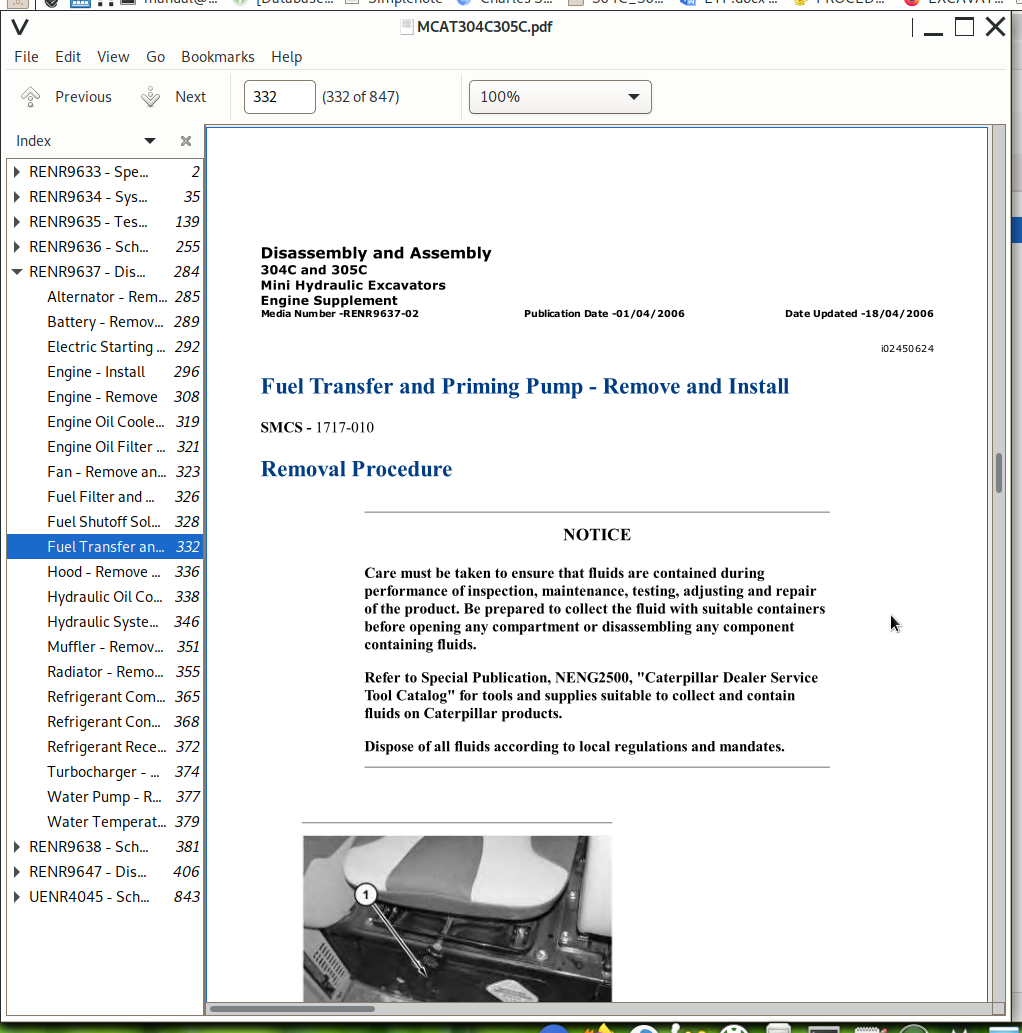
Fuel Transfer and Priming Pump - Remove and Install...332
Hood - Remove and Install...336
Hydraulic Oil Cooler - Remove and Install...338
Hydraulic System Pressure - Release...346
Muffler - Remove and Install...351
Radiator - Remove and Install...355
Refrigerant Compressor - Remove and Install...365
Refrigerant Condenser - Remove and Install...368
Refrigerant Receiver-Dryer - Remove and Install...372
Turbocharger - Remove and Install...374
Water Pump - Remove and Install...377
Water Temperature Regulator - Remove and Install...379
RENR9638 - Schematic (304CCR Mini Hydraulic Excavator Electrical System)...381
Collage...382
Main...397
Features...397
Cover Page...398
Information...0
Component Location...399
Connector Location...400
Specification and Related Manuals...401
Standard Electrical...402
Schematic...403
Machine Views...0
Machine Harness Connector and Component Locations...404
Console Component and Connector Locations...405
RENR9647 - Disassembly and Assembly (304C and 305C Mini Hydraulic Excavators Machine Systems)...406
Accumulator (Hydraulic Pilot) - Remove and Install...409
Blade - Remove and Install...412
Blade Cylinder - Remove and Install...418
Blower Motor (Air Conditioner, Heater) - Remove and Install...424
Boom - Install...430
Boom - Remove...434
Boom Cylinder - Remove and Install...439
Bucket - Remove and Install...446
Bucket Cylinder - Remove and Install...448
Bucket Linkage - Remove and Install...452
Cab - Install...457
Cab - Remove...462
Control Manifold (Pilot Oil) - Assemble - Hydraulic Lockout, Swing Brake and Travel...468
Control Manifold (Pilot Oil) - Disassemble - Hydraulic Lockout, Swing Brake and Travel...471
Control Manifold (Pilot Oil) - Install - Hydraulic Control, Swing Brake and Travel...474
Control Manifold (Pilot Oil) - Remove - Hydraulic Lockout, Swing Brake and Travel...476
Counterweight - Remove and Install...478
Duo-Cone Conventional Seals - Install...486
Evaporator Coil - Remove and Install...493
Final Drive and Travel Motor - Assemble...499
Final Drive and Travel Motor - Disassemble...524
Final Drive and Travel Motor - Install...537
Final Drive and Travel Motor - Remove...540
Front Idler - Remove and Install...543
Front Idler, Recoil Spring and Hydraulic Track Adjuster - Install...545
Front Idler, Recoil Spring and Hydraulic Track Adjuster - Remove...546
Fuel Tank - Remove and Install...547
Heater Core - Remove and Install...550
Heating and Air Conditioning Unit - Install...552
Heating and Air Conditioning Unit - Remove...557
Hydraulic System Pressure - Release...563
Hydraulic Tank - Install...568
Hydraulic Tank - Remove...572
Hydraulic Track Adjusters - Remove and Install...576
Load Control Valve (Boom Cylinder) - Remove and Install...579
Main Control Valve - Assemble...583
Main Control Valve - Disassemble...597
Main Control Valve - Install...612
Main Control Valve - Remove...616
Main Hydraulic Pump - Assemble...621
Main Hydraulic Pump - Disassemble...630
Main Hydraulic Pump - Install...639
Main Hydraulic Pump - Remove...641
Pilot Valve (Auxiliary) - Assemble...643
Pilot Valve (Auxiliary) - Disassemble...645
Pilot Valve (Auxiliary) - Install...647
Pilot Valve (Auxiliary) - Remove...650
Pilot Valve (Blade) - Assemble...653
Pilot Valve (Blade) - Disassemble...659
Pilot Valve (Blade) - Install...665
Pilot Valve (Blade) - Remove...670
Pilot Valve (Boom Swing) - Assemble...676
Pilot Valve (Boom Swing) - Disassemble...678
Pilot Valve (Boom Swing) - Install...680
Pilot Valve (Boom Swing) - Remove...683
Pilot Valve (Travel) - Assemble...686
Pilot Valve (Travel) - Disassemble...698
Pilot Valve (Travel) - Install...709
Pilot Valve (Travel) - Remove...712
Platform - Install...715
Platform - Remove...722
Recoil Spring - Remove and Install...728
Seat - Remove and Install...732
Selector Valve (Alternate Pattern Control) - Install...734
Selector Valve (Alternate Pattern Control) - Remove...737
Sprocket - Remove and Install...740
Stick - Install...742
Stick - Remove...745
Stick Cylinder - Remove and Install...748
Support (Swing Boom) - Install...752
Support (Swing Boom) - Remove...759
Swing Boom Cylinder - Remove and Install...766
Swing Motor and Swing Drive - Assemble...772
Swing Motor and Swing Drive - Disassemble...785
Swing Motor and Swing Drive - Install...799
Swing Motor and Swing Drive - Remove...802
Swivel - Assemble...804
Swivel - Disassemble...809
Swivel - Install...814
Swivel - Remove...817
Track - Remove and Install...820
Track Carrier Roller - Remove and Install...823
Track Roller - Remove and Install...825
Upper Frame and Undercarriage Frame - Connect...828
Upper Frame and Undercarriage Frame - Separate...835
UENR4045 - Schematic (303C, 303.5C, 303.5D, 303.5E, 304C, 304D, 304E, 305C, 305D, 305E, 305.5D and 305.5E Mini Hydraulic Excavators Air Conditioning System)...843
Collage...844
Main...846
Caterpillar Mini Excavator 304C CR, 305C CR Repair Service Manual