
John Deere 318E 320E Skid Steer (EH Controls) FT4/S4 Engines Workshop Repair & Test Service Manual TM13007X19 - MJODTM13007X19.zip
A full Operation and Test technical reference, complete with Electrical Wiring Diagrams, covering the John Deere 318E and 320E Skid Steer Loaders (EH Controls) along with their FT4/S4 Engines — everything a professional technician needs to maintain, troubleshoot, service, and rebuild these machines.
Contained within this John Deere 318E, 320E Skid Steer Loaders (EH Controls) workshop service repair manual:
* Numbered table of contents easy to use so that you can find the information you need fast.
* Detailed sub-steps expand on repair procedure information
* Numbered instructions guide you through every repair procedure step by step.
* Troubleshooting and electrical service procedures are combined with detailed wiring diagrams for ease of use.
* Notes, cautions and warnings throughout each chapter pinpoint critical information.
* Bold figure number help you quickly match illustrations with instructions.
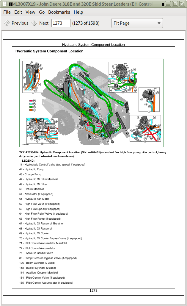
* Detailed illustrations, drawings and photos guide you through every procedure.
* Enlarged inset helps you identify and examine parts in detail.
TM13007X19 - John Deere Skid Steer Loaders (EH Controls) 318E, 320E Operation & Test Service Manual.pdf
TM13007X19 - John Deere Skid Steer Loaders (EH Controls) 318E, 320E Operation & Test Service Manual.epub
Total Pages: 1,531 pages
File Format: PDF/EPUB/MOBI/AZW (PC/Mac/Android/Kindle/iPhone/iPad; bookmarked, ToC, Searchable, Printable)
Language: English
MAIN SECTIONS
Foreword
Manual Identification-READ THIS FIRST!
General Information
Safety
Diagnostic Trouble Codes (DTCs)
Engine Control Unit (ECU) Diagnostic Trouble Codes
Engagement and Monitor Unit (EMU) Diagnostic Trouble Codes
Hydraulic Control Unit (HCU) Diagnostic Trouble Codes
Left Joystick Controller (JSL) Diagnostic Trouble Codes
Right Joystick Controller (JSR) Diagnostic Trouble Codes
Sealed Switch Module (SSM) Diagnostic Trouble Codes
Vehicle Control Unit (VCU) Diagnostic Trouble Codes
Operational Checkout Procedure
Operational Checkout Procedure
Engine
Theory of Operation
Diagnostic Information
Electrical System
System Information
System Diagrams
Sub-System Diagnostics
Monitor Operation
References
Power Train
Theory of Operation
Diagnostic Information
Tests
Hydraulic System
Theory of Operation
Diagnostic Information
Adjustments
Tests
Hydrostatic System
Theory of Operation
Diagnostic Information
Tests
Heating and Air Conditioning
Theory of Operation
Diagnostic Information
Tests
Dealer Fabricated Tools
318E (PIN:1T0318E***J249323-)
320E (PIN:1T0320E***J249291-)
TABLE OF CONTENTS - Expanded Views
9000 - GENERAL INFORMATION
01 - Safety
Add and Operate Attachments Safely
Avoid Backover Accidents
Avoid High-Pressure Fluids
Avoid High-Pressure Oils
Avoid Machine Tip Over
Avoid Unauthorized Machine Modifications
Avoid Work Site Hazards
Clean Debris from Machine
Clean Exhaust Filter Safely
Decommissioning Proper Recycling and Disposal of Fluids and Components
Drive Metal Pins Safely
Follow Safety Instructions
Handle Cab Door Safely
Handle Chemical Products Safely
Inspect and Maintain ROPS
Inspect Machine
Keep Riders Off Machine
Make Welding Repairs Safely
Operate Only If Qualified
Operating On Slopes
Operating or Traveling On Public Roads
Park and Prepare for Service Safely
Prepare for Emergencies
Prevent Battery Explosions
Prevent Fires
Prevent Unintended Machine Movement
Recognize Safety Information
Remove Paint Before Welding or Heating
Service Cooling System Safely
Start Only From Operator's Seat
Stay Clear of Moving Parts
Use and Maintain Seat Belt
Use Steps and Handholds Correctly
Wear Protective Equipment
Work In Ventilated Area
9001 - DIAGNOSTIC TROUBLE CODES (DTC)
10 - Engine Control Unit (ECU) Diagnostic Trouble Codes
000028.00 — Accelerator 3 _ Pedal
000028.01 — Accelerator 3 _ Pedal
000028.03 — Accelerator 3 _ Pedal
000028.04 — Accelerator 3 _ Pedal
000029.03 — Accelerator 2 _ Pedal
000029.04 — Accelerator 2 _ Pedal
000091.03 — Acceleration _ Sensor 1
000091.04 — Acceleration _ Sensor 1
000167.01 — Charge _ Alarm
000167.05 — Charge _ Alarm
000237.13 — Vehicle Identification _ Number
000237.31 — Vehicle Identification _ Number
001485.02 — Main Relay _ ECU
001485.07 — Main Relay _ ECU
003695.14 — Exhaust Filter Cleaning Inhibited By Operator Interface
522243.05 — Start Assist _ Relay
522243.06 — Start Assist _ Relay
522590.12 — Internal _ Supply 1
522596.09 — CAN Comm _ TSC1
522597.09 — TSC1 CAN _ Message
522599.09 — Y_RSS CAN _ Message
522600.09 — Y_EC CAN _ Message
522601.09 — Y_RSS CAN _ Message
522618.09 — EBC1 CAN _ Message
522619.09 — Y_DPFIF CAN _ Message
522623.07 — Accelerator 1-2 Sensor
522624.07 — Accelerator 1-2 Sensor
522744.04 — Internal Driver _ Circuit
522994.04 — Internal Driver _ Circuit
Engine Control Unit (ECU) Diagnostic Trouble Codes
20 - Chassis Control Unit (CCU) Diagnostic Trouble Codes
20 - Engagement and Monitor Unit (EMU) Diagnostic Trouble Codes
000070.02 — Park Brake _ Release Input
000070.04 — Park Brake _ Release Input
000096.03 — Fuel Level _ Sensor
000096.04 — Fuel Level _ Sensor
000158.00 — System Voltage
000158.01 — System Voltage
000162.04 — 2-Speed _ Switch Input
000234.14 — Software Mismatch
000920.05 — Alarm Output
000920.06 — Alarm Output
001196.11 — Anti Theft
001504.04 — Seat Switch _ Input
002000.09 — No ECU Data _ On CAN Bus
002142.09 — No SSM Data _ On CAN Bus
002228.09 — No HCU Data _ On CAN Bus
003413.04 — Door Switch _ Input
003597.03 — 5 Volt Sensor _ Supply 1
003597.04 — 5 Volt Sensor _ Supply 1
521050.04 — Aux Flow On-Off _ Switch Input
521197.04 — Courtesy Light _ Switch Input
522379.05 — Park Brake _ Release Output
522379.06 — Park Brake _ Release Output
522398.02 — Park Brake Run _ Switch Input
522398.04 — Park Brake Run _ Switch Input
522826.00 — Fan Purge _ Switch Input
522826.04 — Fan Purge _ Switch Input
522827.04 — Fan Auto _ Switch Input
522828.03 — Creep Mode _ Switch Input
522828.04 — Creep Mode _ Switch Input
522828.07 — Creep Mode _ Switch Input
522859.04 — Lap Bar _ Switch Input
523217.06 — Hydraulic Valve _ Power 3 to HCU
523218.06 — Propel Valve _ Power 2 to HCU
523219.06 — Hydraulic Valve _ Power Output
523693.03 — Aux Hyd _ Channel 1 Input
523693.04 — Aux Hyd _ Channel 1 Input
523694.03 — Aux Hyd _ Channel 2 Input
523694.04 — Aux Hyd _ Channel 2 Input
523694.12 — Aux Hyd _ Channel 2 Input
523822.04 — High Flow _ Switch Input
523935.05 — Aux Hyd _ Extend Output
523935.06 — Aux Hyd _ Extend Output
523941.05 — Aux Hyd _ Retract Output
523941.06 — Aux Hyd _ Retract Output
523948.05 — Ride Control 1 _ Solenoid Current
523948.06 — Ride Control 1 _ Solenoid Current
523949.05 — Ride Control 2 _ Solenoid Current
523949.06 — Ride Control 2 _ Solenoid Current
524225.04 — Remote Start _ Input
524264.11 — Checksum Error
Engagement and Monitor Unit (EMU) Diagnostic Trouble Codes
30 - Hydraulic Control Unit (HCU) Diagnostic Trouble Codes
000630.13 — Cal Missing _ Or Incomplete
001594.00 — Left Speed _ Sensor Input
001594.01 — Left Speed _ Sensor Input
001594.02 — Left Speed _ Sensor Input
001594.14 — Left Speed _ Sensor Input
001595.00 — Right Speed _ Sensor Input
001595.01 — Right Speed _ Sensor Input
001595.02 — Right Speed _ Sensor Input
001595.14 — Right Speed _ Sensor Input
002201.09 — Right Joystick _ CAN Data
002213.09 — Left Joystick _ CAN Data
002660.07 — Right Joystick _ X-Axis
002661.07 — Right Joystick _ Y-Axis
002697.07 — Left Joystick _ X-Axis
002698.07 — Left Joystick _ Y-Axis
516193.03 — Left Foot Pedal _ Signal 1
516193.04 — Left Foot Pedal _ Signal 1
516193.07 — Left Foot Pedal _ Signal 1
516193.16 — Left Foot Pedal _ Signal 1
516193.18 — Left Foot Pedal _ Signal 1
516194.03 — Left Foot Pedal _ Signal 2
516194.04 — Left Foot Pedal _ Signal 2
516195.03 — Right Foot Pedal _ Signal 2
516195.04 — Right Foot Pedal _ Signal 2
516196.03 — Right Foot Pedal _ Signal 1
516196.04 — Right Foot Pedal _ Signal 1
516196.07 — Right Foot Pedal _ Signal 1
516196.16 — Right Foot Pedal _ Signal 1
516196.18 — Right Foot Pedal _ Signal 1
520652.05 — Bucket Curl _ Solenoid Current
520652.06 — Bucket Curl _ Solenoid Current
520652.16 — Bucket Curl _ Solenoid Current
520653.05 — Bucket Dump _ Solenoid Current
520653.06 — Bucket Dump _ Solenoid Current
520653.16 — Bucket Dump _ Solenoid Current
522377.03 — Boom Sensor _ Signal 1
522377.04 — Boom Sensor _ Signal 1
522377.12 — Boom Sensor _ Signal 1
522377.13 — Boom Sensor _ Signal 1
522436.03 — Bucket Sensor _ Signal 1
522436.04 — Bucket Sensor _ Signal 1
522436.12 — Bucket Sensor _ Signal 1
522436.13 — Bucket Sensor _ Signal 1
522437.03 — Bucket Sensor _ Signal 2
522437.04 — Bucket Sensor _ Signal 2
522447.05 — Right Pump _ Fwd Sol Current
522447.06 — Right Pump _ Fwd Sol Current
522447.16 — Right Pump _ Fwd Sol Current
522448.05 — Right Pump _ Rev Sol Current
522448.06 — Right Pump _ Rev Sol Current
522448.16 — Right Pump _ Rev Sol Current
522449.05 — Left Pump _ Rev Sol Current
522449.06 — Left Pump _ Rev Sol Current
522449.16 — Left Pump _ Rev Sol Current
522450.05 — Left Pump _ Fwd Sol Current
522450.06 — Left Pump _ Fwd Sol Current
522450.16 — Left Pump _ Fwd Sol Current
523217.03 — Hydraulic Valve _ Power 3 to HCU
523217.04 — Hydraulic Valve _ Power 3 to HCU
523218.03 — Propel Valve _ Power 2 to HCU
523218.04 — Propel Valve _ Power 2 to HCU
523219.03 — Hydraulic Valve _ Power 1 to HCU
523219.04 — Hydraulic Valve _ Power 1 to HCU
523378.03 — Boom Sensor _ Signal 2
523378.04 — Boom Sensor _ Signal 2
523411.05 — Boom Down _ Solenoid Current
523411.06 — Boom Down _ Solenoid Current
523411.16 — Boom Down _ Solenoid Current
523414.05 — Boom Up _ Solenoid Current
523414.06 — Boom Up _ Solenoid Current
523414.16 — Boom Up _ Solenoid Current
Hydraulic Control Unit (HCU) Diagnostic Trouble Codes
40 - Left Joystick Controller (JSL) Diagnostic Trouble Codes
002697.03 — Left Joystick _ X-Axis
002697.04 — Left Joystick _ X-Axis
002697.13 — Left Joystick _ X-Axis
002697.14 — Left Joystick _ X-Axis
002698.03 — Left Joystick _ Y-Axis
002698.04 — Left Joystick _ Y-Axis
002698.13 — Left Joystick _ Y-Axis
002698.14 — Left Joystick _ Y-Axis
Left Joystick Controller (JSL) Diagnostic Trouble Codes
50 - Right Joystick Controller (JSR) Diagnostic Trouble Codes
002660.03 — Right Joystick _ X-Axis
002660.04 — Right Joystick _ X-Axis
002660.13 — Right Joystick _ X-Axis
002660.14 — Right Joystick _ X-Axis
002661.03 — Right Joystick _ Y-Axis
002661.04 — Right Joystick _ Y-Axis
002661.13 — Right Joystick _ Y-Axis
002661.14 — Right Joystick _ Y-Axis
Right Joystick Controller (JSR) Diagnostic Trouble Codes
60 - Sealed Switch Module (SSM) Diagnostic Trouble Codes
0000629.12 — Controller Fault
002033.09 — VCU CAN Comm
002634.04 — Ignition Relay
002634.05 — Ignition Relay
523850.04 — SSM Button 15
523850.09 — SSM Button 15
523852.04 — SSM Button 14
523852.09 — SSM Button 14
523854.04 — SSM Button 13
523854.09 — SSM Button 13
523855.04 — SSM Button 12
523855.09 — SSM Button 12
523856.04 — SSM Button 11
523856.09 — SSM Button 11
523857.04 — SSM Button 10
523857.09 — SSM Button 10
523858.04 — SSM Button 9
523858.09 — SSM Button 9
523860.04 — SSM Button 8
523860.09 — SSM Button 8
523861.04 — SSM Button 7
523861.09 — SSM Button 7
523862.04 — SSM Button 6
523862.09 — SSM Button 6