
John Deere 5085M 5100M 5100MH 5100ML 5115M 5115ML FT4 Tractor Diagnostics Repair Service Manual TM134219 PDF - MJODTM134219.zip
A full diagnostic testing service guide, complete with Electrical Wiring Diagrams, covering John Deere FT4 Tractors models 5085M, 5100M, 5100MH, 5100ML, 5115M, and 5115ML (S.N. MY2014-, MY2014-Dec-2014, MY2016-), plus workshop-level details for maintaining, troubleshooting, and servicing these machines the way expert technicians do.
The workshop diagnosis tests technical manual for John Deere Tractors 5085M, 5100M, 5100MH, 5100ML, 5115M, and 5115ML contains:
* Numbered table of contents easy to use so that you can find the information you need fast.
* Detailed sub-steps expand on repair procedure information
* Numbered instructions guide you through every repair procedure step by step.
* Troubleshooting and electrical service procedures are combined with detailed wiring diagrams for ease of use.
* Notes, cautions and warnings throughout each chapter pinpoint critical information.
* Bold figure number help you quickly match illustrations with instructions.
* Detailed illustrations, drawings and photos guide you through every procedure.
* Enlarged inset helps you identify and examine parts in detail.
tm134219 - 5085M, 5100M, 5100MH, 5100ML, 5115M, and 5115ML (FT4) Tractors Diagnostics Technical Manual.pdf
tm134219 - 5085M, 5100M, 5100MH, 5100ML, 5115M, and 5115ML (FT4) Tractors Diagnostics Technical Manual.epub
Total Pages: 2,593 pages
File Format: PDF/EPUB/MOBI/AZW (PC/Mac/Android/Kindle/iPhone/iPad; bookmarked, ToC, Searchable, Printable)
Language: English
MAIN SECTIONS
Foreword
General Information
Safety
General References
Technical Specific References
Diagnostic Trouble Codes
CCU Code Diagnostics
ECU Code Diagnostics
EIC Code Diagnostics
HCU Code Diagnostics
ICC Code Diagnostics
JDL Code Diagnostics
PTR Code Diagnostics
Observable Symptoms and System Diagnostics
General References
Engine Diagnostics
Fuel, Air Intake, Exhaust, and Cooling Diagnostics
Electrical Diagnostics
Electronic Control Unit Diagnostics
Drive Systems and Transmission Diagnostics
Steering and Brakes Diagnostics
Hydraulic Diagnostics
Cab/Open Operator`s Station Diagnostics
Engine
General References
Engine Component and Connector Information
Engine Tests and Adjustments
Fuel, Air Intake, Exhaust, and Cooling
General References
Fuel, Air Intake, Exhaust, and Cooling Theory of Operation
Electrical General and Theory of Operation
General References
Turn Signal Switch and Warning Lights
Wipers (Two Speed)
Rear Wipers
Instrument Cluster Control (ICC)
Electrohydraulic Control Unit (EHC)
Hitch Control Unit (HCU)
Power Train Reverser (PTR)
Chassis Control Unit (CCU) (PR Transmission)
Chassis Control Unit (CCU) (SS Transmission)
Engine Control Unit (ECU)
Controller Area Network
Electrical Schematics
General References
Key Switch, Starter, and Alternator (SE01)
Neutral Start (SS Transmission) (SE02A)
Neutral Start (PR Transmission) (SE02B)
Accessory Power (SE03)
Horn (SE04)
Light Switch and Headlights (SE05A)
Turn and Brake Lights (SE05B)
Cab Work Lighting (SE05C)
Open Operator Station Work Lighting (SE05D)
Warning Lights (SE06)
Junction Block Power (SE09)
Implement Connector (SE10)
Loader Lights (SE12)
Back-Up Alarm (SE13A)
Beacon Light (SE13B)
Mid-Mount SCV (SE14)
Power Outlets (SE15)
Heating (SE16)
Air Conditioning (SE17)
Front Wiper (Two Speed) (SE19)
Rear Wiper (SE21)
Dome Light, Door Switch, and Radio (SE22)
Air Seat (SE23)
Instrument Cluster Control (ICC) (SE24)
Seat Switch, Rear PTO Switch, and Wheel Speed Sensor (SE25)
ELX Relay and Fuses (SE26)
Mechanical Front-Wheel Drive (MFWD) (SE27)
Brake Switch (SE28)
Chassis Control Unit (CCU) (PR Transmission) (SE29A)
Electrohydraulic Control Unit (EHC) (SE29B)
Hitch Control Unit (HCU) (SE29C)
Chassis Control Unit (CCU) (SS Transmission) (SE29D)
Engine Control Unit (ECU) (SE30)
Controller Area Network (SE32)
AutoTrac Universal (ATU) (SE33)
JDLink (SE34)
Electrical Components and Connectors
General References
Key Switch, Starter, and Alternator (SE01)
Neutral Start (SS Transmission) (SE02A)
Neutral Start (PR Transmission) (SE02B)
Accessory Power (SE03)
Horn (SE04)
Light Switch and Headlights (SE05A)
Turn and Brake Lights (SE05B)
Cab Work Lighting (SE05C)
Open Operator Station Work Lighting (SE05D)
Warning Lights (SE06)
Junction Block Power (SE09)
Implement Connector (SE10)
Loader Lights (SE12)
Back-Up Alarm (SE13A)
Beacon Light (SE13B)
Mid-Mount SCV (SE14)
Power Outlets (SE15)
Heating (SE16)
Air Conditioning (SE17)
Front Wiper (Two Speed) (SE19)
Rear Wiper (SE21)
Dome Light, Door Switch and Radio (SE22)
Air Seat (SE23)
Instrument Control Cluster (ICC) (SE24)
Seat Switch, Rear PTO Switch, and Wheel Speed Sensor (SE25)
ELX Relay and Fuses (SE26)
Mechanical Front-Wheel Drive (MFWD) (SE27)
Brake Switch (SE28)
Chassis Control Unit (CCU) (PR Transmission) (SE29A)
Electrohydraulic Control Unit (EHC) (SE29B)
Hitch Control Unit (HCU) (SE29C)
Chassis Control Unit (CCU) (SS Transmission) (SE29D)
Engine Control Unit (ECU) (SE30)
Controller Area Network (SE32)
AutoTrac Universal (ATU) (SE33)
JDLink (SE34)
Fuses and Relays
Ground Points
Interconnects
Wiring Harnesses
Electrical Tests and Adjustments
General References
Tests and Adjustments
Electronic Control Units
General References
Calibrations, Preliminary Checks and Operational Checks
Theory of Operation
Schematics
Component and Connector Information
Tests and Adjustments
Chassis Control Unit (CCU)
Engine Control Unit (ECU)
Engine Interface Control Unit (EIC)
Hitch Control Unit (HCU)
Instrument Cluster Control Unit (ICC)
Power Train Reverser (PTR)
Drive Systems and Transmissions
General References
Calibrations, Preliminary Checks and Operational Checks
Creeper Theory of Operation
Differential Theory of Operation
Differential Lock Theory of Operation
Final Drive Theory of Operation
Rear PTO Theory of Operation
High Crop Axle Theory of Operation
MFWD Theory of Operation
PR Transmission Theory of Operation
PR Plus Transmission Theory of Operation
SS Transmission Theory of Operation
Drive Systems Schematics
Transmission Schematics
Drive Systems Component and Connector Information
Transmission Component and Connector Information
Drive Systems Tests and Adjustments
Transmission Tests and Adjustments
Steering and Brakes
General References
Brake Calibrations, Preliminary Checks and Operational Checks
Steering Calibrations, Preliminary Checks and Operational Checks
Brake Theory of Operation
Steering Theory of Operation
Brake Schematics
Steering Schematics
Brake Component and Connector Information
Steering Component and Connector Information
Brake Tests and Adjustments
Steering Tests and Adjustments
Hydraulics
General References
Hydraulic Calibrations, Preliminary and Operational Checks
General Hydraulics Theory of Operation
Electrohydraulic Hitch Theory of Operation
Mechanical Hitch Theory of Operation
Front Hitch Theory of Operation
Hydraulic Filter Theory of Operation
Hydraulic Pump Theory of Operation
Dual Mid-Mount SCV Theory of Operation
Power Beyond Theory of Operation
Quick Disconnect Coupler Theory of Operation
Dual Rear SCV Theory of Operation
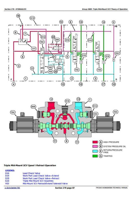
Triple Mid-Mount SCV Theory of Operation
Triple Rear SCV Theory of Operation
Schematics
Component and Connector Information
Tests and Adjustments
Cab/Open Operator`s Station
General References
Calibrations, Preliminary Checks and Operational Checks
HVAC Theory of Operation
Seat Theory of Operation
Schematics
Component and Connector Information
Tests and Adjustments
Special Tools
General References
Dealer Fabricated and Service Tools
tm134219 - 5085M, 5100M, 5100MH, 5100ML, 5115M, and 5115ML (FT4) Tractors Diagnostic Technical Manual
Table of Contents
Foreword
Section 210: General Information
Group 05A: Safety
Work In Ventilated Area
Recognize Safety Information
Avoid Backover Accidents
Prevent Machine Runaway
Avoid Contact with Agricultural Chemicals
Clean Vehicle of Hazardous Pesticides
Use a Safety Chain
Work in Clean Area
Decommissioning: Proper Recycling and Disposal of Fluids and Components
Avoid Harmful Asbestos Dust
Avoid Hot Exhaust
Clean Exhaust Filter Safely
Handle Fuel Safely—Avoid Fires
Prepare for Emergencies
Handle Fluids Safely—Avoid Fires
Avoid High-Pressure Fluids
Install All Guards
Use Proper Lifting Equipment
Illuminate Work Area Safely
Live With Safety
Service Machines Safely
Support Machine Properly
Remove Paint Before Welding or Heating
Park Machine Safely
Stay Clear of Rotating Drivelines
Follow Safety Instructions
Use Proper Tools
Service Tires Safely
Keep ROPS Installed Properly
Construct Dealer-Made Tools Safely
Practice Safe Maintenance
Understand Signal Words
Replace Safety Signs
Avoid Heating Near Pressurized Fluid Lines
Wear Protective Clothing
Service Accumulator Systems Safely
Handling Batteries Safely
Handle Agricultural Chemicals Safely
Service Cooling System Safely
Use Steps and Handholds Correctly
Transport Tractor Safely
Group 05B: General References
General Information - Summary of References
Regions and Country Versions
Deliver Safely
Glossary of Terms
Information Available in Sections, Groups and Subgroups
Trademarks
Group 05C: Technical Specific References
Features and Accessories
Metric Bolt and Screw Torque Values
Unified Inch Bolt and Screw Torque Values
Section 211: Diagnostic Trouble Codes
Group CCU: CCU Code Diagnostics
CCU 000090.03 - Rear PTO Oil Temperature Sensor Circuit Voltage High
CCU 000090.04 - Rear PTO Oil Temperature Sensor Circuit Voltage Low
CCU 000096.03 - Fuel Level Sensor Circuit Voltage High
CCU 000096.04 - Fuel Level Sensor Circuit Voltage Low
CCU 000237.02 - VIN Security Data Conflict
CCU 000237.14 - VIN Security Not Enabled
CCU 000237.31 - VIN Security Messages Missing
CCU 000567.05 - Front Differential Lock Solenoid Circuit Fault
CCU 000569.05 - Rear Differential Lock Solenoid Circuit Fault
CCU 000628.02 - CCU EOL Data Fault
CCU 000629.12 - CCU Control Unit Fault
CCU 000630.14 - Rear PTO Configuration Invalid
CCU 000976.04 - Rear PTO WEO Sensor Open
CCU 001638.00 - Hydraulic Oil Temperature Very Hot
CCU 001638.03 - Hydraulic Oil Temperature Sensor Circuit Voltage High
CCU 001638.04 - Hydraulic Oil Temperature Sensor Circuit Voltage Low
CCU 001638.16 - Hydraulic Oil Temperature High
CCU 001883.00 - Rear PTO Overspeed
CCU 001883.01 - Rear PTO Underspeed
CCU 002818.31 - Operator Presence Switch Not Activated
CCU 003509.03 - Sensor Supply Voltage Out of Range High
CCU 003509.04 - Sensor Supply Voltage Out of Range Low
CCU 522384.14 - Rear PTO High Reverse
CCU 523316.04 - Switched Supply Voltage Low
CCU 523844.12 - Differential Lock Braking Disabled
CCU 523907.02 - PTO Remote Enable Switch Conflict