
John Deere GreenStar 2 (GS2, AMS) Technical Service Manual TM1061 - PDF - MJODTM1061.zip
A full technical service guide (testing and diagnostics) featuring complete electrical schematics for the John Deere GreenStar 2, packed with every detail shops need to service, troubleshoot, fix, and rebuild the unit just like expert technicians.
The John Deere GreenStar 2 (AMS, GreenStar2, GS2) service manual covers:
* Numbered table of contents easy to use so that you can find the information you need fast.
* Detailed sub-steps expand on repair procedure information
* Numbered instructions guide you through every repair procedure step by step.
* Troubleshooting and electrical service procedures are combined with detailed wiring diagrams for ease of use.
* Notes, cautions and warnings throughout each chapter pinpoint critical information.
* Bold figure number help you quickly match illustrations with instructions.
* Detailed illustrations, drawings and photos guide you through every procedure.
* Enlarged inset helps you identify and examine parts in detail.
TM1061 - John Deere GreenStar 2 Worldwide Edition Technical Manual.pdf
TM1061 - John Deere GreenStar 2 Worldwide Edition Technical Manual.epub
Total Pages: 1,295 pages
File Format: PDF (Internal Links, Bookmarked, Table of Contents, Searchable, Printable, high quality)
Language: English
MAIN SECTIONS
Foreword
General
Safety
Guidance Safety
Safety Signs
GreenStar Display 1800 General Information
GreenStar Display 2100/2600 General Information
GreenStar Component Identification
GreenStar Component Software Identification
Technician Mode Procedure
Generating and Sending a Debug File
GreenStar 2 Diagnostic Trouble Codes
External Display Control Diagnostic Trouble Codes
FIELD DOCFIELD DOC is a trademark of Deere & Company
Basic Warning Messages
FIELD DOCFIELD DOC is a trademark of Deere & Company
Connect Warning Messages
GreenStar Display Diagnostic Trouble Codes
Guidance - SSU Diagnostic Trouble Codes - AutoTrac Controller
System
Guidance - AutoTrac Stop/Exit Codes
Guidance - Universal Row Guidance Diagnostic Trouble Codes
iTEC Pro Stop/Exit Codes
Original GreenStar Display Caution, Warning, and Fault Code
Messages
Original STARFIRE Receiver Warnings
StarFire 300 Receiver Diagnostic Trouble Codes
STARFIRE Receiver (StarFire 3000 and iTC) Diagnostic Trouble
Codes
Task Controller Warnings
Terrain Compensation Module (TCM) Diagnostic Trouble Codes
Observable Symptoms
Active Implement Guidance
End of Life Cycle for AMS Displays
End of Life Cycle for AMS Receivers
Electrical System Diagnosis and Test
Accessing GreenStar 2 Diagnostic Trouble Codes and Addresses
Accessing Original GreenStar Fault Codes
GreenStar 2 Diagnostic Trouble Codes
GreenStar 2 Diagnostic Addresses
Original GreenStar Display Caution, Warning, & Fault Codes
CAN Bus Type Identification
CAN Bus Diagnostics - Type A
CAN Bus Diagnostics - Type B
CAN Bus Diagnostics - Type C
CAN Bus Diagnostics - Type D
CAN Bus Diagnostics - Type E
CAN Bus Diagnostics - Type F
CAN Bus Diagnostics - Type G
CAN Bus Diagnostics - Type H
Control Unit SSU Overall Diagnostics - AutoTrac Controller
Data Card neergleb Diagnostics
Documentation Diagnostics Type Identification
Documentation Diagnostics - Type A
Documentation Diagnostics - Type B
Documentation Diagnostics - Type C
Documentation Diagnostics - Type D
External Display Control Diagnostics
GPS Receiver Diagnostics (Non - Deere)
GreenStar Display Type Identification
GreenStar Display Diagnostics - Type A
GreenStar Display Diagnostics - Type B
GreenStar Display Diagnostics - Type C
GreenStar Lightbar Diagnostics
Guidance - AutoTrac Type Identification
Guidance - AutoTrac Diagnostics - Type A
Guidance - AutoTrac Diagnostics - Type B
Guidance - AutoTrac Diagnostics - Type C
Guidance - AutoTrac Diagnostics - Type D
Guidance - AutoTrac Rowsense Integrated
Guidance - iGuide Diagnostics - Type Identification
Guidance - iGuide Diagnostics - Type A
Guidance - iGuide Diagnostics - Type B
Guidance - iSteer Diagnostics
Guidance - Parallel Tracking Type Identification
Guidance - Parallel Tracking Diagnostics - Type A
Guidance - Parallel Tracking Diagnostics - Type B
Guidance - AutoTrac Rowsense Universal
iGrade Diagnostics
iTEC Pro Diagnostics
Performance Monitor Diagnostics
Power Type Identification
Power Diagnostics - Type A
Power Diagnostics - Type B
RTK Base Station Type Identification
RTK Base Station Diagnostics - Type A
RTK Base Station Diagnostics - Type B
RTK Vehicle Type Identification
RTK Vehicle Diagnostics - Type A
RTK Vehicle Diagnostics - Type B
StarFire Receiver Type Identification
StarFire Receiver Diagnostics - Type A
StarFire Receiver Diagnostics - Type B
StarFire Receiver Diagnostics - Type C
StarFire Receiver Diagnostics - Type D
StarFire Receiver Diagnostics - Type E
StarFire iTC Radar Signal Diagnostics
Surface Water Pro
Swath Belgreen Control Diagnostics
Connector Information (end views, numbers)
Connector Repair Procedures
tm1061 - 2 Technical Manual
Table of Contents
Foreword
Section 210: General
Group 05A: Safety
Recognize Safety Information
Understand Signal Words
Follow Safety Instructions
Handle Electronic Components and Brackets Safely
Read Operator’s Manuals for ISOBUS Controllers
Prepare for Emergencies
Park Machine Safely
Use Seat Belt Properly
Operating the Tractor Safely
Operate Safely
Stay Clear of Rotating Drivelines
Keep Riders Off Machine
Work in Clean Area
Work In Ventilated Area
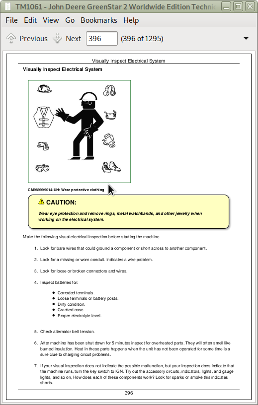
Wear Protective Clothing
Illuminate Work Area Safely
Practice Safe Maintenance
Use Proper Tools
Decommissioning — Proper Recycling and Disposal of Fluids and Components
Live With Safety
Group 05B: Guidance Safety
Use AutoTrac Controller on Approved Vehicles
Operate Guidance Systems Safely
Group 05C: Safety Signs
Implement Detected
Auxiliary Control
AutoTrac Detected
Approaching Impassable Boundary
Malfunction of Implement Height Switch Detected
Unexpected NH3 Flow Detected
Unexpected NH3 Flow Detected
Unexpected Chemical Flow Detected
NH3 Diagnostic Tests
Diagnostic Tests
Group 10A: GreenStar Display 1800 General Information
General Information
Front of Display
Back of Display
Getting Started With Your Display
Group 10B: GreenStar Display 2100/2600 General Information
General Information
Front of Display
Back of Display
Screen Navigation - Touchscreen
Screen Navigation - External Display Control
Screen Navigation - Bezel buttons on back of display (secondary screen navigation)
Screen Layout
GREENSTAR Display 2100/2600 Power Up
External Display Control Buttons
Group 10C: GreenStar Component Identification
Identification Labels
GREENSTAR GREENSTAR is a trademark of Deere & Company Display 2100
GREENSTAR GREENSTAR is a trademark of Deere & Company Display 2600
GREENSTAR GREENSTAR is a trademark of Deere & Company STARFIRE (Original) or STARFIRE iTC Receiver
Data Card
Group 10D: GreenStar Component Software Identification
GREENSTAR GREENSTAR is a trademark of Deere & Company 2 Component Software Identifications
Message Center
Group 10E: Technician Mode Procedure
Technician Mode Procedure
Group 10F: Generating and Sending a Debug File
Generating a Debug File on GreenStar Display 1800
Generating a Debug File on GreenStar Display 2100 or 2600
Transferring Debug Files and screen shots on GreenStar Display 1800
Transferring Debug Files and screen shots on GreenStar Display 1800 to data card, if LCD has failed
Transferring Setup Information on GreenStar Display 1800 to data card, if LCD has failed
Transferring a Debug File on GreenStar Display 2100/2600
Section 211: GreenStar 2 Diagnostic Trouble Codes
Group A: External Display Control Diagnostic Trouble Codes
UIM 000168.03 - External Display Control Switched power too high
UIM 000168.04 - External Display Control Switched power too low
UIM 000628.02 - External Display Control Internal Fault
UIM 000629.12 - External Display Control Internal Error
UIM 000639.14 - Indicates that the CAN Bus message sent by the implement is faulty or incomplete
UIM 523526.10 - Indicates button J is defective
UIM 523527.10 - Indicates button I is defective
UIM 523528.10 - Indicates button H is defective
UIM 523529.10 - Indicates button G is defective
UIM 523530.10 - Indicates button F is defective
UIM 523531.10 - Indicates button E is defective
UIM 523532.10 - Indicates button D is defective
UIM 523533.10 - Indicates button C is defective
UIM 523534.10 - Indicates button B is defective
UIM 523535.10 - Indicates button A is defective
UIM 523536.10 - Indicates Menu button is defective
UIM 523537.10 - Indicates Abort button is defective
UIM 523538.10 - Indicates Confirm button is defective
UIM 523910.02 - Indicates External Display Control unit has an internal fault
Group B: FIELD DOCFIELD DOC is a trademark of Deere & Company Basic Warning Messages
ID 200 - GPS communications failure
ID 201 - No GPS position information
ID 202 - No GPS differential correction
ID 245 - Data card has file left open
ID 246 - Data card full error
Group C: FIELD DOCFIELD DOC is a trademark of Deere & Company Connect Warning Messages
ID 550 - No Controller
ID 551 - Rawson Selected Warning
ID 552 - Multiple Seeding Operations
ID 553 - Incorrect Model Selected
ID 554 - Recording Not Allowed
ID 555 - Target Rate Change Warning
ID 556 - Lime and Pesticide Warning
ID 557 - Raven no Actual Warning
Group D: GreenStar Display Diagnostic Trouble Codes
VTi 08 - Directory creation error
VTi 12 - Missing update file
VTi 14 - File read error
VTi 16 - File write error
VTi 37 - Invalid file handle
VTi 44 - Checksum failed
VTi 45 - Controller file invalid
VTi 47 - Incompatible hardware
VTi 48 - Update file invalid
VTi 51 - User aborted
VTi 55 - Controller flash erase failed
VTi 56 - Message missing colon
VTi 57 - Record too long
VTi 58 - Invalid record length
VTi 59 - Sequence error
VTi 60 - Controller received odd address
VTi 61 - Controller timed out
VTi 62 - NOR flash reprogramming problem
VTi 63 - Unknown controller response
VTi 81 - Reprogramming session failed
VTi 000158.03 - Indicates display's switch supply voltage high - greater than 32.0 VDC
VTi 000158.04 - Indicates display's switched supply voltage low - less than 8.5 VDC
VTi 000168.03 - Indicates display's unswitched supply voltage high
VTi 000168.04 - Indicates display's unswitched supply voltage Low
VTi 000609.12 - Indicates permanent channel down condition on SP1 communication lines.
VTi 000920.05 - Open circuit detected when driving speaker
VTi 001386.00 - Indicates display unit temperature high
VTi 001386.01 - Indicates display unit temperature low
VTi 003597.02 - Indicates a display internal supply voltage fault
VTi 003598.02 - Indicates a display internal supply voltage fault
VTi 003599.02 - Indicates a display internal supply voltage fault
VTi 521780 - Indicates overcurrent condition detected on USB circuit
VTi 523304 - Indicates channel failure on encoder after a full rotation.
VTi 523310.12 - Indicates a display's non volatile memory read/write failure
VTi 523319.03 - Indicates display's switched supply voltage high
VTi 523319.04 - Indicates display's switched supply voltage low
VTi 523525.10 - Indicates Home button is held or pressed for more than 60 seconds.
VTi 523526.10 - Indicates J button is held or pressed for more than 60 seconds.
VTi 523527.10 - Indicates I button is held or pressed for more than 60 seconds
VTi 523528.10 - Indicates H button is held or pressed for more than 60 seconds
VTi 523529.10 - Indicates J button is held or pressed for more than 60 seconds.
VTi 523530.10 - Indicates F button is held or pressed for more than 60 seconds.
VTi 523531.10 - Indicates E button is held or pressed for more than 60 seconds.
VTi 523532.10 - Indicates D button is held or pressed for more than 60 seconds.
VTi 523533.10 - Indicates C button is held or pressed for more than 60 seconds.
VTi 523534.10 - Indicates B button is held or pressed for more than 60 seconds.
VTi 523535.10 - Indicates A button is held or pressed for more than 60 seconds.
VTi 523536.10 - Indicates application button is held or pressed for more than 60 seconds.
VTi 523537.10 - Indicates X (cancel) button is held or pressed for more than 60 seconds.
VTi 523538.10 - Indicates check button is held or pressed for more than 60 seconds.
VTi 523771.03 - Indicates CCD High Line Voltage High
VTi 523771.04 - Indicates CCD High Line Voltage Low
VTi 523772.03 - Indicates CCD Low Line Voltage High
VTi 523772.04 - Indicates CCD High Line Voltage Low
VTi 523773.03 - Indicates vehicle CAN High line voltage high
VTi 523773.04 - Indicates vehicle CAN High line voltage low
VTi 523774.03 - Indicates vehicle CAN Low line voltage High
VTi 523774.04 - Indicates vehicle CAN Low line voltage Low
VTi 524050.12 - Real Time Clock Failure
VTi 524215.03 - Indicates Implement CAN High line voltage high
VTi 524215.04 - Indicates Implement CAN High line voltage low
VTi 524217.03 - Indicates Implement CAN Low line voltage high
VTi 524217.04 - Indicates Implement CAN Low line voltage low
Group E: Guidance - SSU Diagnostic Trouble Codes - AutoTrac Controller System
SSU 000168.03 - Unswitched supply voltage high
SSU 000168.04 - Unswitched supply voltage low
SSU 000232.09 - StarFire Differential Status message missing
SSU 000517.09 - GPS speed message missing
SSU 000628.12 - SSU programming
SSU 000630.13 - SSU calibration fault/not calibrated
SSU 003509.03 - Sensor voltage too high
SSU 003509.04 - Sensor voltage too low.
SSU 003509.05 - Sensor supply current below normal or open circuit
SSU 003509.06 - Sensor supply current above normal or grounded circuit