
John Deere 896 Auger Platform Workshop Repair Service Manual PDF TM2265 - MJODTM2265.zip
A full-service Diagnostics and Repair guide for the John Deere 896 Auger Platform, complete with electrical wiring schematics, delivering the technical detail needed to service, troubleshoot, fix, and overhaul the equipment just like an expert technician.
The workshop Diagnosis Repair Service manual for the John Deere 896 Auger Platform contains:
* Numbered table of contents easy to use so that you can find the information you need fast.
* Detailed sub-steps expand on repair procedure information
* Numbered instructions guide you through every repair procedure step by step.
* Troubleshooting and electrical service procedures are combined with detailed wiring diagrams for ease of use.
* Notes, cautions and warnings throughout each chapter pinpoint critical information.
* Bold figure number help you quickly match illustrations with instructions.
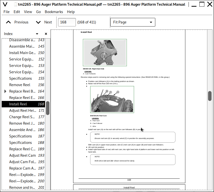
* Detailed illustrations, drawings and photos guide you through every procedure.
* Enlarged inset helps you identify and examine parts in detail.
TM2265 - John Deere 896 Auger Platform All Inclusive Technical Manual (Diagnosis Operation Tests Repair Service).PDF
Total Pages: 411 pages
File Format: PDF (bookmarked, ToC, Searchable, Printable, high quality)
Language: English
MAIN SECTIONS
Foreword
Service Technician Response
General
Safety
Specifications
General Information
Lubrication
Platform Drives
General Information
Components
Knife Drive Sheave and Belt
Reel Drive
Auger Drives
Conditioner Driveline
Main Gear Case
Reel
Reel
Reel Cam and Reel Cam Followers
Reel Teeth, Reel Bar, and Reel Bar Bearings
Hydraulic Driven Reel (If Equipped)
Augers
General Information
Components
Adjust Strippers to Augers
Auger Bearings and End Shafts
Upper and Lower Augers
Cutterbar and Cutting Components
General Information
Knife Sections
Knives
Knife Drive
Cutterbar
Electrical System
General Information
Turn/Warning Lights
Connector Repair
Conditioner
General Information
Conditioner Roll Adjustments
Conditioner Roll Bearings Repair
Conditioner Rolls Repair
tm2265 - 896 Auger Platform
Table of Contents
Foreword
Service Technician Response
Section 10: General
Group 05: Safety
Recognize Safety Information
Understand Signal Words
Prepare for Emergencies
Avoid High-Pressure Fluids
Park Machine Safely
Support Machine Properly
Wear Protective Clothing
Work in Clean Area
Service Machines Safely
Work In Ventilated Area
Illuminate Work Area Safely
Replace Safety Signs
Avoid Harmful Asbestos Dust
Use Proper Lifting Equipment
Remove Paint Before Welding or Heating
Avoid Heating Near Pressurized Fluid Lines
Practice Safe Maintenance
Practice Safe Service Procedures
Use Proper Tools
Construct Dealer-Made Tools Safely
Dispose of Waste Properly
Live With Safety
Group 10: Specifications
896 Auger Platform (Specifications and design subject to change without notice.)
Metric Bolt and Screw Torque Values
Unified Inch Bolt and Screw Torque Values
Service Recommendations For O-Ring Boss Fittings
Service Recommendations For 37° Flare and 30° Cone Seat Connectors
Group 15: General Information
General Information
Platform Lift Lockout
Knockdown Bar
Metric And Customary Design
Repair Components
Unauthorized Modifications
Care Of V-Belts
Care of Chains
Install O-Ring Connector Link
Tighten Bearing Locking Collar
Group 20: Lubrication
Grease
Gear Case Oil
Alternative and Synthetic Lubricants
Mixing of Lubricants
Lubricant Storage
Perform Lubrication and Maintenance
Section 20: Platform Drives
Group 05: General Information
Stay Clear of Rotating Drivelines
Platform Operation
Group 10: Components
Left-Hand Upper Auger Drive
Left-Hand Lower Auger Drive
Right-Hand Upper Auger Drive
Group 15: Knife Drive Sheave and Belt
Service Equipment and Tools
Other Material
Specifications
Remove Knife Drive Sheave
Install Knife Drive Sheave
Replace and Adjust Knife Drive Belt
Align Knife Drive Belt
Group 20: Reel Drive
Specifications
Replace Reel Drive Belt
Adjust Reel Drive Belt
Replace and Adjust Reel Drive Chain
Group 25: Auger Drives
Service Equipment and Tools
Other Material
Specifications
Replace Left-Hand Upper or Lower Auger Drive Chain and Sprockets
Adjust Upper and Lower Auger Drive Chains
Group 30: Conditioner Driveline
Essential or Recommended Tools
Service Parts Kits
Other Material
Specifications
Remove and Install Conditioner Driveline
Repair Conditioner Driveline
Group 35: Main Gear Case
Essential or Recommended Tools
Service Equipment and Tools
Other Material
Service Parts Kits
Specifications
Remove Main Gear Case
Disassemble and Inspect Main Gear Case
Assemble Main Gear case
Install Main Gear Case
Section 30: Reel
Group 15: Reel
Service Equipment and Tools
Specifications
Remove Reel
Replace Reel Bearings
Replace Reel End Shaft
Install Reel
Adjust Reel Height
Change Reel Speed (Mechanical Drive)
Remove Reel Jackshaft And Bearing
Assemble And Install Jackshaft Assembly
Group 20: Reel Cam and Reel Cam Followers
Specifications
Replace Reel Cam Followers
Adjust Reel Cam
Adjust Cam Follower Engagement
Replace Cam Arms
Group 25: Reel Teeth, Reel Bar, and Reel Bar Bearings
Reel—Exploded View
Remove and Install Reel Bar, Bearings and Teeth
Group 30: Hydraulic Driven Reel (If Equipped)
Service Equipment and Tools
Other Material
Service Parts Kits
Specifications
Hydraulic Driven Reel Operation and Component Location
Test Hydraulic Reel Drive
Remove and Install Reel Hydraulic Pump and Sprockets
Remove and Install Chain Tensioner
Replace Speed Sensor
Disassemble and Assemble Reel Hydraulic Pump
Inspect Reel Hydraulic Pump
Remove and Install Reel Hydraulic Motor, Sprockets, and Slotted Disk
Disassemble, Inspect and Assemble Reel Hydraulic Motor
Remove and Install Reel Hydraulic Valve Block
Disassemble, Inspect and Assemble Reel Hydraulic Valve Block
Section 40: Augers
Group 05: General Information
Specifications
Augers
Group 15: Components
Left-Hand Upper Auger Drive
Left-Hand Lower Auger Drive
Group 20: Adjust Strippers to Augers
Specifications
Adjust Upper and Lower Strippers to Augers
Adjust Center Strippers to Lower Auger
Group 25: Auger Bearings and End Shafts
Service Equipment and Tools
Other Material
Specifications
Replace Right-Hand Lower Auger Bearing
Replace Right-Hand Upper Auger Bearing
Replace Left-Hand Auger Bearings
Replace Auger End Shaft
Group 30: Upper and Lower Augers
Service Equipment and Tools
Other Material
Specifications
Remove Upper and Lower Augers
Install Upper and Lower Augers
Remove Auger Flighting
Install Auger Flighting
Straighten Augers
Section 50: Cutterbar and Cutting Components
Group 05: General Information
Practice Safe Service Procedures
Cutterbar
Knife Sections
Knife Overlap
Knife Hold-Downs
Group 15: Knife Sections
Essential or Recommended Tools
Specifications
Replace Bolt-On Knife Sections
Replace Center Knife Sections
Group 20: Knives
Specifications
Time Knives
Knife Overlap
Remove Knives
Install Knives
Group 25: Knife Drive
Essential or Recommended Tools
Service Equipment and Tools
Other Material
Specifications
Remove and Disassemble Knife Drive
Inspect Knife Drive Assembly
Assemble and Install Knife Drive
Group 30: Cutterbar
Specifications
Adjust Regular Knife Hold-Downs
Adjust Non-Clog Knife Hold-Downs
Install Regular Cutterbar Guards
Install Non-Clog Cutterbar Guards
Section 60: Electrical System
Group 05: General Information
Platform Electrical System Description
Platform Wiring Harness Diagram (Model Year —2009)
Platform Wiring Harness Diagram (Model Year 2010— )
Wiring Harness Adapter Diagram (Model Year 2010— )
Group 10: Turn/Warning Lights
Replace Turn/Warning Light Fixture
Replace Turn/Warning Light Bulb
Group 15: Connector Repair
Essential or Recommended Tools
Other Material
Electrical Connector Handling
Use Contact Cleaner and Di-electric Grease
Replace WEATHER PACK Connector
Install WEATHER PACK Terminal
Replace METRI-PACK (Push Type) Connectors
Harness Repair—Splice Connector
Section 70: Conditioner
Group 05: General Information
Practice Safe Service Procedures
Conditioner
Group 15: Conditioner Roll Adjustments
Adjust Conditioner Roll Spacing
Adjust Conditioner Roll Pressure
Adjust Conditioner Roll Timing
Group 20: Conditioner Roll Bearings Repair
Essential and Recommended Tools
Specifications
Replace Lower Conditioner Roll Bearings
Replace Upper Conditioner Roll Bearings
Group 25: Conditioner Rolls Repair
Essential or Recommended Tools
Specifications
Remove Conditioner and Conditioner Rolls
Inspect Conditioner Components
Install Conditioner Rolls and Conditioner
John Deere 896 Auger Platform All Inclusive Service Technical Manual (TM2265)