
Hitachi Zaxis 160LC-5G (ZX160LC-5G) Excavator Workshop Repair Service Manual TM12648 PDF - MHITTM12648.zip
Full Service Repair Workshop Manual for the Hitachi Zaxis 160LC-5G Excavator, containing every piece of shop-level guidance needed to service, fix, and rebuild this machine the way trained technicians do.
The Hitachi Zaxis 160LC-5G (ZX160LC-5G) repair and workshop manual covers:
* Numbered table of contents easy to use so that you can find the information you need fast.
* Detailed sub-steps expand on repair procedure information
* Numbered instructions guide you through every repair procedure step by step.
* Notes, cautions and warnings throughout each chapter pinpoint critical information.
* Bold figure number help you quickly match illustrations with instructions.
* Detailed illustrations, drawings and photos guide you through every procedure.
* Enlarged inset helps you identify and examine parts in detail.
TM12648 - Hitachi Zaxis 160LC-5G Excavator Technical Manual - Repair.pdf
TM12650 - Hitachi Excavadora Zaxis160LC-5G.pdf
TM12649 - Hitachi Excavatrice Zaxis160LC-5G.pdf
TM12651 - Hitachi Escavadeira Zaxis160LC-5G.pdf
PRODUCT DETAILS:
Total Pages: 724 pages
File Format: PDF/EPUB/MOBI/AZW (PC/Mac/Android/Kindle/iPhone/iPad; bookmarked, ToC, Searchable, Printable)
Language: English Spanish French Portuguese
Models: John Deere / HITACHI - Excavator - 1FFDBGH0__C230001
TABLE OF CONTENTS...1
Section 00: General Information...10
Group 01: Safety...10
Recognize Safety Information...14
Understand Signal Words...15
Follow Safety Instructions...16
Prepare for Emergencies...17
Wear Protective Clothing...18
Protect Against Noise...19
Inspect Machine...20
General Precautions for Cab...21
Use Handholds and Steps...22
Adjust the Operator's Seat...23
Ensure Safety Before Rising From or Leaving Operator’s Seat...24
Fasten Your Seat Belt...25
Move and Operate Machine Safely...26
Operate Only From Operator's Seat...27
Jump Starting...28
Keep Riders Off Machine...29
Precautions for Operations...30
Investigate Job Site Beforehand...31
Install OPG Guard...33
Restriction of Attachment Installation...34
Provide Signals for Jobs Involving Multiple Machines...35
Confirm Direction of Machine to be Driven...36
Drive Machine Safely...37
Avoid Injury From Rollaway Accidents...41
Avoid Injury From Back-Over and Swing Accidents...42
Keep Person Clear From Working Area...44
Never Position Bucket Over Anyone...45
Avoid Undercutting...46
Avoid Tipping...47
Never Undercut a High Bank...49
Dig With Caution...50
Operate With Caution...51
Avoid Power Lines...52
Precautions for Lightning...53
Object Handling...54
Protect Against Flying Debris...55
Park Machine Safely...56
Handle Fluids Safely−Avoid Fires...57
Transport Safely...58
Practice Safe Maintenance...59
Warn Others of Service Work...61
Support Machine Properly...62
Stay Clear of Moving Parts...63
Prevent Parts From Flying...64
Avoid Injury from Attachment Falling Accident...65
Prevent Burns...66
Replace Rubber Hoses Periodically...67
Avoid High-Pressure Fluids...68
Prevent Fires...70
Evacuating in Case of Fire...72
Beware of Exhaust Fumes...73
Precautions for Welding and Grinding...74
Avoid Heating Near Pressurized Fluid Lines...75
Remove Paint Before Welding or Heating...76
Beware of Asbestos and Silicon Dust and Other Contamination...77
Prevent Battery Explosions...78
Service Air Conditioning System Safely...79
Handle Chemical Products Safely...80
Dispose of Waste Properly...81
Never Ride Attachment...82
Precautions for Communication Terminal...83
FCC Notifications to User...84
Before Returning the Machine to the Customer...85
Notes on Protection of Operator’s Station When the Machine Rolls Over...86
Group 3: Torque Values...12
Metric Bolt and Cap Screw Torque Values...90
Additional Metric Cap Screw Torque Values...92
Unified Inch Bolt and Cap Screw Torque Values...94
Service Recommendations for 37° Flare and 30° Cone Seat Connectors...96
Service Recommendations for O-Ring Boss Fittings...98
Service Recommendations for Flared Connections—Straight or Tapered Threads...100
Service Recommendations for Flat Face O-Ring Seal Fittings...102
O-Ring Boss Fittings in Aluminum Housing Service Recommendations—Excavators...104
O-Ring Face Seal Fittings With SAE Inch Hex Nut and Stud End for High-Pressure Service Recommendations...107
O-Ring Face Seal Fittings With Metric Hex Nut and Stud End for Standard Pressure Service Recommendations...109
O-Ring Face Seal Fittings With Metric Hex Nut and Stud End for High-Pressure Service Recommendations...112
Service Recommendations for Metric Series Four Bolt Flange Fitting...115
Service Recommendations For Inch Series Four Bolt Flange Fittings...117
Inch Series Four Bolt Flange Fitting for High-Pressure Service Recommendations...119
Service Recommendations For Non-Restricted Banjo (Adjustable) Fittings...121
Service Recommendations For O-Ring Boss Fittings With Shoulder...124
Metric 24° O-Ring Seal DIN 20078 Service Recommendations...127
Section 01: Tracks...131
Group 0130: Track System...131
Track Roller Remove and Install...136
Track Roller Disassemble and Assemble...140
Track Roller Pressure Test...143
Track Carrier Roller Remove and Install...146
Metal Face Seals Repair...149
Track Shoe Remove and Install...152
Track Chain Remove and Install...155
Track Chain Disassemble and Assemble...162
Track Chain Repair to Replace Broken Part...165
Sprocket Remove and Install...171
Front Idler Remove and Install...174
Front Idler Disassemble and Assemble...176
Track Adjuster and Recoil Spring Remove and Install...180
Track Adjuster and Recoil Spring Disassemble and Assemble...182
Track Adjuster Cylinder Disassemble and Assemble...189
Section 02: Axles, Differentials, and Suspension Systems...191
Group 0250: Axle Shaft, Bearings, and Reduction Gears...191
Travel Gear Case Remove and Install...196
Travel Gear Case Disassemble and Assemble...200
Group 0260: Hydraulic System...191
Travel Motor and Park Brake Remove and Install...215
Travel Motor and Park Brake Disassemble and Assemble...219
Park Brake Valve Disassemble and Assemble...230
Travel Motor and Park Brake Start-Up Procedure...233
Metal Face Seal Install...234
Section 04: Engine...240
Group 0400: Removal and Installation...240
Engine Remove and Install...251
Section 05: Engine Auxiliary System...261
Group 0510: Cooling Systems...261
Radiator Remove and Install...266
Hydraulic Oil Cooler Remove and Install...270
Charge Air Cooler Remove and Install...274
Fan, Fan Guard, and Fan Shroud Remove and Install...276
Coolant Recovery Tank Remove and Install...279
Group 0560: External Fuel Supply Systems...261
Fuel Tank Remove and Install...286
Section 07: Damper Drive (Flex Coupling)...291
Group 0752: Elements...291
Damper Drive (Flex Coupling) Remove and Install...296
Section 17: Frame or Supporting Structure...300
Group 1740: Frame Installation...300
Welding on Machine...303
Group 1749: Chassis Weights...300
Counterweight Remove and Install...309
Section 18: Operator's Station...313
Group 1800: Removal and Installation...313
Cab Remove and Install...325
Group 1810: Operator Enclosure...313
Windshield Remove and Install...338
Windshield Disassemble and Assemble...340
Sliding Windows Remove and Install...350
Windowpanes Remove and Install...352
Windowpanes Dimensions...353
Group 1821: Seat and Seat Belt...313
Seat Remove and Install...363
Seat Belt Remove and Install...365
Mechanical Suspension Seat Disassemble and Assemble...370
Air Suspension Seat Disassemble and Assemble...376
Group 1830: Heating and Air Conditioning...313
R134a Refrigerant Cautions and Proper Handling...382
R134a Refrigerant Oil Information...383
R134a Refrigerant Recovery, Recycling, and Charging Station Installation Procedure...385
Recover R134a Refrigerant...387
Flush and Purge Air Conditioning System...388
Evacuate R134a System...391
Charge R134a System...393
Air Conditioner Compressor Remove and Install...395
Condenser Remove and Install...397
Heater and Air Conditioner Remove and Install...398
Heater and Air Conditioner Blower Motor Remove and Install...403
Receiver-Dryer Remove and Install...409
Section 19: Sheet Metal and Styling...411
Group 1910: Hood or Engine Enclosure...411
Hood Remove and Install...414
Section 33: Excavator...416
Group 3302: Buckets...416
Bucket Remove and Install...419
Adjust Bucket Pivot End Play...420
Bucket Pin-Up Data...422
Group 3340: Frames...416
Bucket Links Remove and Install...427
Arm Remove and Install...430
Boom Remove and Install...434
Inspect Pins, Bushings, and Bosses—Front Attachment...442
Cylinder Specifications...445
Bushings and Seal Remove and Install...446
Group 3360: Hydraulic System...416
Apply Vacuum to Hydraulic Oil Tank...450
Hydraulic Oil Cleanup Procedure Using Portable Filter Caddy...452
Pump 1 and 2 Remove and Install...453
Pump 1 and 2 Disassemble and Assemble...458
Pump 1 and 2 Inspection...476
Pump 1 and 2 Start-Up Procedure...481
Pump 1 and 2 Regulator Remove and Install...483
Pump 1 and 2 Regulator Disassemble and Assemble...485
Pilot Pump Remove and Install...488
Pilot Pump Disassemble and Assemble...491
Pilot Pressure Regulating Valve and Filter Remove and Install...493
Pilot Pressure Regulating Valve and Filter Disassemble and Assemble...495
Pilot Shutoff Solenoid Valve Remove and Install...497
Pilot Shutoff Solenoid Valve Disassemble and Assemble...500
Solenoid Valve Manifold Remove and Install...502
Solenoid Valve Remove and Install—Power Dig/Travel Speed (SG), Arm Regenerative (SC), and Dig Regenerative (SF) Valves...504
Solenoid Valve Disassemble and Assemble—Power Dig/Travel Speed (SG), Arm Regenerative (SC), and Dig Regenerative (SF) Valves...507
Pilot Valve (Left and Right) Remove and Install...509
Pilot Valve (Left and Right) Disassemble and Assemble...512
Travel Pilot Valve Remove and Install...521
Travel Pilot Valve Disassemble and Assemble...524
Pilot Signal Manifold Remove and Install...528
Pilot Signal Manifold Disassemble and Assemble...530
Control Valve Remove and Install...533
Control Valve Halves Disassemble and Assemble...538
Control Valve (5-Spool) Disassemble and Assemble...540
Control Valve (4-Spool) Disassemble and Assemble...566
Hydraulic Oil Tank Remove and Install...589
Hydraulic Oil Tank Disassemble and Assemble...595
Restriction Valve Remove and Install...599
Hydraulic Oil Cooler Bypass Valve Remove and Install...601
Boom Cylinder Remove and Install...603
Boom Cylinder Disassemble and Assemble...608
Arm Cylinder Remove and Install...614
Arm Cylinder Disassemble and Assemble...618
Bucket Cylinder Remove and Install...624
Bucket Cylinder Disassemble and Assemble...628
Hydraulic Cylinder Bleed Procedure...634
Section 43: Swing or Pivoting System...635
Group 4350: Mechanical Drive Elements...635
Swing Gear Case Remove and Install...639
Swing Gear Case Disassemble and Assemble...642
Swing Gear Case Start-Up Procedure...652
Upperstructure Remove and Install...654
Swing Bearing Remove and Install...659
Swing Bearing Disassemble and Assemble...662
Swing Bearing Upper Seal Install...665
Swing Bearing Lower Seal Install...666
Group 4360: Hydraulic System...635
Center Joint Remove and Install...672
Center Joint Disassemble and Assemble...676
Center Joint Air Test...680
Swing Motor and Park Brake Remove and Install...681
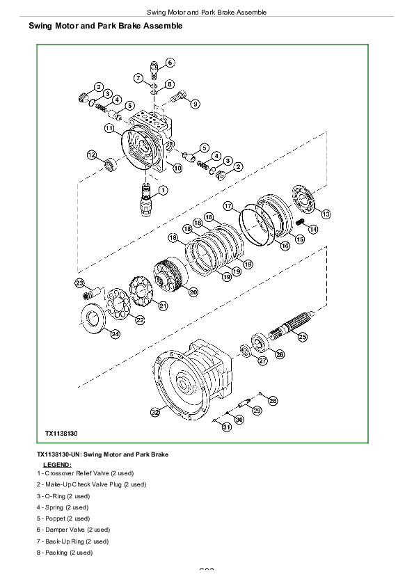
Swing Motor and Park Brake Disassemble...684
Swing Motor and Park Brake Inspection...688
Swing Motor and Park Brake Assemble...693
Swing Motor and Park Brake Start-Up Procedure...697
Crossover Relief Valve and Make-Up Check Valve Remove and Install...698
Make-Up Check Valve Disassemble and Assemble...702
Swing Park Brake Check Valve and Orifice Remove and Install...704
Section 99: Dealer Fabricated Tools...707
Group 9900: Dealer Fabricated Tools...707
DF1063 Lift Bracket...710
ST4920 Track Recoil Spring Disassembly and Assembly Tool...712
DFT1087 Track Recoil Spring Disassembly and Assembly Guard Tool...717
DFT1110 Spacer...718
DFT1130 Adapter...719
DFT1036A Travel Gear Case Nut Wrench...720
DFT1109 Holding Bar...721
Center Joint (Rotary Manifold) Lifting Tool...722
DFT1220 Swing Gear Case Nut Spanner Wrench...724
Hitachi Zaxis 160LC-5G Excavator Repair Service Manual (TM12648)