
John Deere PowerTech 8.1 L 6081 Diesel Engine Component Technical Manual CTM86 (CTM86) - MJODCTM86.zip
A fully comprehensive component technical guide featuring electrical schematics for John Deere PowerTech 8.1L diesel engines, containing every piece of shop-level information needed to service, troubleshoot, overhaul, and rebuild these engines the way professional technicians do (covering diagnosis, operation, testing, repair, servicing, and fault-finding).
The John Deere Base Engine Technical Manual for PowerTech 8.1L diesel engines is a workshop service manual that includes:
* Numbered table of contents easy to use so that you can find the information you need fast.
* Detailed sub-steps expand on repair procedure information
* Numbered instructions guide you through every repair procedure step by step.
* Troubleshooting and electrical service procedures are combined with detailed wiring diagrams for ease of use.
* Notes, cautions and warnings throughout each chapter pinpoint critical information.
* Bold figure number help you quickly match illustrations with instructions.
* Detailed illustrations, drawings and photos guide you through every procedure.
* Enlarged inset helps you identify and examine parts in detail.
ctm86 - PowerTech 8.1 L Diesel Engines Base Engine - (Worldwide Edition) Component Technical Manual.PDF
ctm86 - PowerTech 8.1 L Diesel Engines Base Engine - (Worldwide Edition) Component Technical Manual.epub
Total Pages: 767 pages
File Format: PDF (bookmarked, ToC, Searchable, Printable, high quality) & EPUB/MOBI/AZW for Kindle etc.
Language: English
ctm86 - PowerTech™ 8.1 LDiesel EnginesBase Engine -: (Worldwide Edition)
Component Technical Manual
Table of Contents
Foreword
About this Manual
Identification Views Serial Number ( —199,999) Non Emissions Certified, and Tier I Emissions Certified Engines
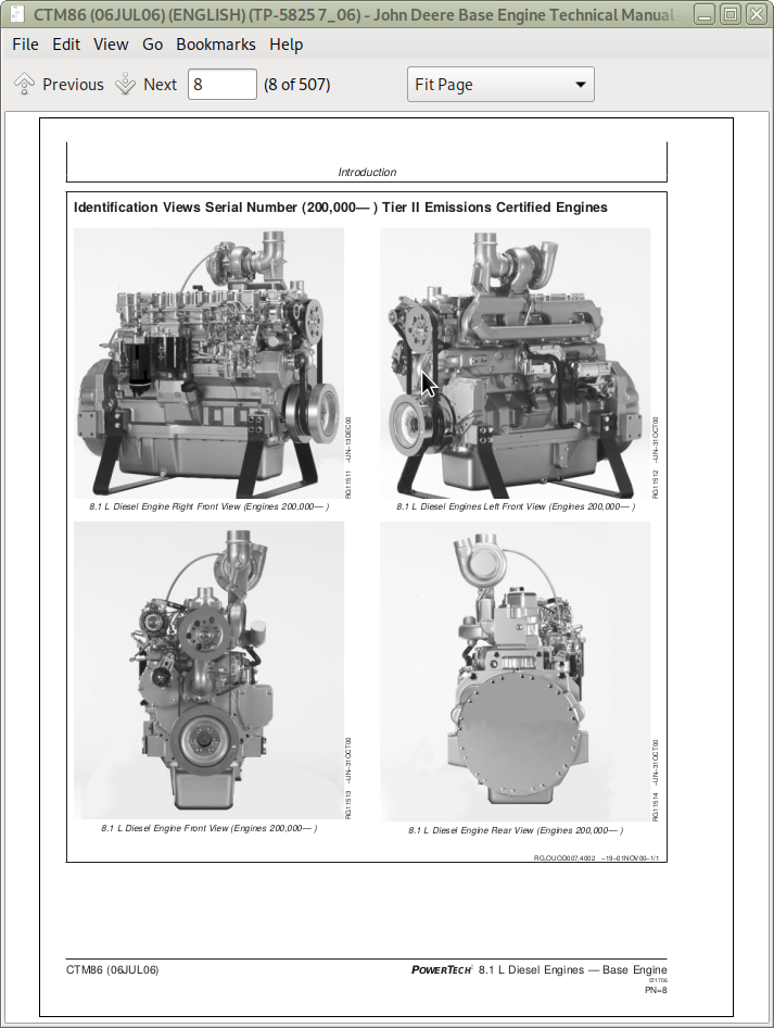
Identification Views Serial Number (200,000— ) Tier II Emissions Certified Engines
Section 01: General
Group 000: Safety
Handle Fluids Safely—Avoid Fires
Handle Starting Fluid Safely
Handling Batteries Safely
Prepare for Emergencies
Avoid High-Pressure Fluids
Wear Protective Clothing
Service Machines Safely
Work In Ventilated Area
Work in Clean Area
Install Fan Guards
Avoid Hot Parts
Remove Paint Before Welding or Heating
Avoid Heating Near Pressurized Fluid Lines
Illuminate Work Area Safely
Use Proper Lifting Equipment
Construct Dealer-Made Tools Safely
Practice Safe Maintenance
Use Proper Tools
Decommissioning — Proper Recycling and Disposal of Fluids and Components
Live With Safety
Group 001: Engine Identification
Engine Model Designation
Engine Serial Number Plate Information
Engine Option Code Label
Group 002: Fuels, Lubricants and Coolant
Diesel Fuel
Diesel Fuel Additive Products
Bio-Diesel Fuel
Lubricity of Diesel Fuel
Handling and Storing Diesel Fuel
Testing Diesel Fuel
Fuel Filters
Diesel Engine Break-In Oil — Non-Emissions Certified and Certified Tier 1, Tier 2, Tier 3, Stage I, Stage II, and Stage III
Diesel Engine Oil — Non-Emissions Certified and Certified Tier 1 and Stage I
Extended Diesel Engine Oil Service Intervals — Non-Emissions Certified and Certified Tier 1 and Stage I
Alternative and Synthetic Lubricants
Mixing of Lubricants
OILSCAN OILSCAN is a registered trademark of Deere & Company. and CoolScan CoolScan is a registered trademark of Deere & Company.
Grease
Diesel Engine Coolant (engine with wet sleeve cylinder liners)
Diesel Engine Coolants, Supplemental Additive Information
Testing Diesel Engine Coolant
Replenishing Supplemental Coolant Additives (SCAs) Between Coolant Changes
Operating in Warm Temperature Climates
Flush and Service Cooling System
Disposing of Coolant
Section 02: Repair and Adjustments
Group 010: Engine Rebuild
Engine Overhaul Guidelines
Engine Repair Stand
Safety Precautions
Install Adapters on Engine Repair Stand
Engine Lifting Procedure
Clean Engine
Disconnect Turbocharger Oil Inlet Line
Mount Engine on Repair Stand
Engine Disassembly Sequence for Overhaul
Sealant Application Guidelines
6081 Engine Assembly Sequence After Overhaul
Engine Break-In Guidelines
Perform Engine Break-In
Check Crankcase Ventilation System
Check Air Intake System
Check Exhaust System
Check and Service Cooling System
Check Electrical System
General Tune-Up Recommendations
Group 020: Cylinder Head and Valves Repair and Adjustment S. N. ( —199,999)
Check and Adjust Valve Clearance Serial Number ( —199,999)
Check Valve Lift Serial Number ( —199,999)
Remove Cylinder Head Serial Number ( —199,999)
Head Gasket Inspection and Repair Sequence Serial Number ( —199,999)
Disassemble and Inspect Rocker Arm Shaft Assembly Serial Number ( —199,999)
Assemble Rocker Arm Shaft Assembly Serial Number ( —199,999)
Measure Valve Recess Serial Number ( —199,999)
Preliminary Cylinder Head and Valve Checks Serial Number ( —199,999)
Remove Valve Assembly Serial Number ( —199,999)
Inspect and Measure Valve Springs Serial Number ( —199,999)
Inspect Valve Spring Caps, Wear Caps, and Retainer Locks Serial Number ( —199,999)
Clean Valves Serial Number ( —199,999)
Inspect and Measure Valves Serial Number ( —199,999)
Grind (Reface) Valves Serial Number ( —199,999)
Inspect and Clean Cylinder Head Serial Number ( —199,999)
Check Cylinder Head Combustion Face Flatness Serial Number ( —199,999)
Measure Cylinder Head Thickness Serial Number ( —199,999)
Clean Valve Guides Serial Number ( —199,999)
Measure Valve Guides Serial Number ( —199,999)
Knurl Valve Guides Serial Number ( —199,999)
Clean and Inspect Valve Seats Serial Number ( —199,999)
Measure Valve Seats Serial Number ( —199,999)
Grind Valve Seats Serial Number ( —199,999)
Remove Valve Seat Inserts Serial Number ( —199,999)
Install Valve Seat Inserts Serial Number ( —199,999)
Inspect and Clean Cylinder Head Nozzle Bore Serial Number ( —199,999)
Clean and Inspect Push Rods Serial Number ( —199,999)
Clean and Inspect Top Deck of Cylinder Block Serial Number ( —199,999)
Measure Cylinder Liner Standout (Height Above Block) Serial Number ( —199,999)
Assemble Valve Assembly Serial Number ( —199,999)
Install Cylinder Head and Cap Screws Serial Number ( —199,999)
Torque-to-Yield Flanged-Head Cap Screws—Grade 180 Marked “SPECIAL” Serial Number ( —199,999)
Install Rocker Arm Assembly Serial Number ( —199,999)
Inspect and Clean Ventilator Outlet Hose Serial Number ( —199,999)
Complete Final Assembly of Injection Pump Side of Engine Serial Number ( —199,999)
Complete Final Assembly on Exhaust Manifold Side of Engine Serial Number ( —199,999)
Perform Engine Break-In Serial Number ( —199,999)
Group 021: Cylinder Head and Valves Repair and Adjustment S. N. (200,000— )
Check Valve Clearance — Serial Number (200,000— )
Adjust Valve Clearance Serial Number (200,000— )
Check Valve Lift Serial Number (200,000— )
Remove Cylinder Head Serial Number (200,000— )
Diagnosing Head Gasket Joint Failures - Serial Number (200,000— )
Head Gasket Diagnostic Charts - Serial Number (200,000— )
Head Gasket Inspection and Repair Sequence - Serial Number (200,000— )
Inspect Rocker Arm Assembly - Serial Number (200,000— )
Disassemble and Assemble Rocker Arm Assembly - Serial Number (200,000— )
Measure Valve Recess - Serial Number (200,000— )
Preliminary Cylinder Head and Valve Checks - Serial Number (200,000— )
Remove Valve Assembly - Serial Number (200,000— )
Inspect and Measure Valve Springs - Serial Number (200,000— )
Inspect Valve Spring Caps, Wear Caps, and Retainer LocksSerial Number (200,000— )
Clean Valves - Serial Number (200,000— )
Inspect and Measure Valves - Serial Number (200,000— )
Inspect and Measure Valves - Serial Number (200,000— )
Grind (Reface) Valves - Serial Number (200,000— )
Inspect and Clean Cylinder Head - Serial Number (200,000— )
Check Cylinder Head Combustion Face Flatness - Serial Number (200,000— )
Measure Cylinder Head Thickness - Serial Number (200,000— )
Clean Valve Guides - Serial Number (200,000— )
Measure Valve Guides - Serial Number (200,000— )
Knurl Valve Guides - Serial Number(200,000— )
Clean and Inspect Valve Seats - Serial Number (200,000— )
Measure Valve Seats - Serial Number (200,000— )
Grind Valve Seats - Serial Number (200,000— )
Remove Valve Seat Inserts and Measure Bores in Cylinder Head - Serial Number (200,000— )
Install Valve Seat Inserts - Serial Number (200,000— )
Inspect and Clean Cylinder Head Nozzle Bore - Serial Number (200,000— )
Clean and Inspect Push Rods - Serial Number (200,000— )
Clean and Inspect Top Deck of Cylinder Block - Serial Number (200,000— )
Measure Cylinder Liner Standout (Height Above Block) - Serial Number (200,000— )
Assemble Valve Assembly - Serial Number (200,000— )
Install Cylinder Head and Cap Screws - Serial Number (200,000— )
Torque-to-Yield Flanged-Head Cap Screws—Grade 180 Marked “SPECIAL” - Serial Number (200,000— )
Install Rocker Arm Assembly - Serial Number (200,000— )
Inspect and Clean Ventilator Outlet Hose - Serial Number (200,000— )
Complete Final Assembly of Fuel Pump Side of Engine - Serial Number (200,000— )
Complete Final Assembly on Exhaust Manifold Side of Engine - Serial Number (200,000— )
Perform Engine Break-In - Serial Number (200,000— )
Cylinder Head—Preparation and Measurement
Cylinder Head — Thickness Measurement
Group 030: Cylinder Block, Liners, Pistons, and Rods Repair and Adjustment
Preliminary Liner, Piston, and Rod Checks
Connecting Rods—General Information
Remove Pistons and Connecting Rod Assemblies
Measure Cylinder Liner Standout (Height Above Block)
Install Liner Shims—If Required
Remove Cylinder Liners
Deglaze Cylinder Liners
Cylinder Liner — Cleaning
Disassemble Piston and Rod Assembly
Clean Pistons
Visually Inspect Pistons
Check Piston Ring Groove Wear
Inspect Piston Pin and Bore
Visually Inspect Cylinder Liners
Cylinder Liner Manufacturing Date Code Explanation
Determine Piston-to-Liner Clearance
Inspect Rod and Cap
Inspect Piston Pins and Bushings
Remove Piston Pin Bushing, Clean and Inspect Pin Bore
Measure Liner Flange
Inspect and Measure Connecting Rod Bearings
Piston Pin Bushing — Installation
Complete Disassembly of Cylinder Block (If Required)
Remove and Clean Piston Cooling Orifices
Clean Cylinder Block
Cylinder Block — Inspect and Reclaim
Measure Cylinder Block
Install Piston Cooling Orifices and Gallery Plugs
Install Packing on Cylinder Liner and O-Rings in Block
Install Cylinder Liner in Block
Install Piston and Connecting Rod
Connecting Rod Cap Screw — Torque Procedure
Check Engine Rotation for Excessive Tightness
Complete Final Assembly
Group 040: Crankshaft, Main Bearings and Flywheel Repair and Adjustment
Crankshaft and Main Bearing Failure Analysis
Crankshaft Rear Oil Seal and Wear Sleeve General Information
Remove Crankshaft Rear Oil Seal and Wear Sleeve
Crankshaft Rear Oil Seal and Wear Sleeve Handling Precautions
Install Crankshaft Rear Oil Seal and Wear Sleeve
Crankshaft Dual Damper — Removal
Install Unitized Front Crankshaft Oil Seal
Inspect Vibration Damper
Check Crankshaft End Play
Remove Crankshaft Vibration Damper
Remove Crankshaft Front Oil Seal and Wear Sleeve
Remove and Install Timing Gear Cover—Engine Installed in Vehicle (8000 Series Tractors)
Remove Timing Gear Cover—Engine Removed
Inspect and Measure Flywheel
Check Flywheel Housing Face Runout
Check Flywheel Face Flatness
Check Pilot Bearing Bore Concentricity
Remove Flywheel
Remove SAE 1 Flywheel Housing
Remove SAE 2 and 3 Flywheel Housing
Replace Flywheel Ring Gear
Remove and Install Rear Oil Seal Housing—Engine Installed in Vehicle (8000 Series Tractors)
Remove Rear Oil Seal Housing—Engine Removed
Remove Main Bearing Caps
Check Main Bearing Oil Clearance
Remove Connecting Rod Caps and Remove Crankshaft
Crankshaft — Inspection
Measure Assembled I.D. of Bearings and O.D. of Crankshaft Journals
Main Bearing Cap Line Bore Specifications
Thrust Bearing New Part Specifications
Crankshaft Grinding Guidelines
Crankshaft Grinding Specifications
Replace Crankshaft Gear
Inspect Thrust Bearings
Remove and Clean Piston Cooling Orifices
Install Main Bearings and Crankshaft
Install Crankshaft Rear Oil Seal Housing
Check Crankshaft Rear Oil Seal Housing Runout
Crankshaft Rear Oil Seal and Wear Sleeve Handling Precautions
Install Crankshaft Rear Oil Seal and Wear Sleeve Assembly
Install Timing Gear Cover
Install Front Wear Sleeve
Install Crankshaft Front Oil Seal
Install Unitized Front Crankshaft Oil Seal
Install Vibration Damper
Crankshaft Dual Damper — Installation
Install SAE 2 and 3 Flywheel Housing
Install Flywheel & Flex Plates - Option Code 1502
Install Flywheel
Install SAE 1 Flywheel Housing
Complete Final Assembly
Group 050: Camshaft and Timing Gear Train Repair and Adjustment
Check Camshaft End Play and Measure Gear Backlash
Remove Vibration Damper and Timing Gear Cover
Remove, Inspect, and Install Crankshaft Gear-Driven Auxiliary Drive—If Equipped
Remove Camshaft
Remove Camshaft Gears
Measure Thrust Washer Thickness
Inspect and Measure Camshaft Followers
Visually Inspect Camshaft
Measure Camshaft Journal O.D. and Bushing I.D.
Measure Camshaft Lobe Lift
Install Camshaft Gears
Service Camshaft Bushings Using JDG602 Adapter Set
Service Camshaft Bushings Using JDG606 Adapter Set
Install Camshaft
Install Thrust Washer and Timing Gear Cover
Complete Final Assembly
Group 060: Lubrication System Repair and Adjustment
Diagnosing Lubrication System Malfunctions
Oil Filter Base and Oil Pressure Regulating Valve Housing Assembly
Top-Load Oil Filter Assembly
Remote Oil Filter Assembly
Changing Top-Load Oil Filter
Remove and Install Oil Filter Base and Oil Pressure Regulating Valve Housing
Engine Oil Cooler Assembly
Remove, Inspect, and Install Engine Oil Cooler
Remove, Inspect, and Install Oil Pressure Regulating Valve, Oil Filter Bypass Valve, and Oil Cooler Bypass Valve
Remove Oil Pressure Regulating Valve — Top Load Oil Filter
Install Oil Pressure Regulating Valve — Top Load Oil Filter
Remove Engine from 8000 Tractors for Access to Engine Oil Pump
Remove Oil Pan
Check Crankshaft Gear-to-Oil Pump Drive Gear Backlash
Remove Engine Oil Pump
Inspect and Clean Oil Pump
Check Drive Shaft End Play
Check Drive Shaft Side Movement
Check Pumping Gear Backlash
Inspect Oil Pump Drive Gear
Adjust Oil Pump Set Screw
Install Engine Oil Pump