
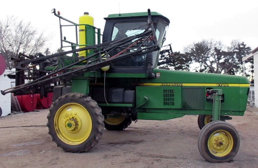
John Deere 6700 Self-Propelled Sprayer Operation and Test Service Manual (TM1834) PDF - MJODTM1834.zip
This is a full-service Diagnostics and Tests guide (with Electrical Wiring Diagrams) for the John Deere 6700 Self-Propelled Sprayer, offering shop-level detail to service, troubleshoot, fix, and rebuild the machine the way trained technicians do.
The Diagnostics workshop manual for the John Deere 6700 Self-Propelled Sprayer contains:
* Numbered table of contents easy to use so that you can find the information you need fast.
* Detailed sub-steps expand on repair procedure information
* Numbered instructions guide you through every repair procedure step by step.
* Troubleshooting and electrical service procedures are combined with detailed wiring diagrams for ease of use.
* Notes, cautions and warnings throughout each chapter pinpoint critical information.
* Bold figure number help you quickly match illustrations with instructions.
* Detailed illustrations, drawings and photos guide you through every procedure.
* Enlarged inset helps you identify and examine parts in detail.
TM1834 - John Deere 6700 Self-Propelled Sprayers Technical Manual (Operation and Tests).PDF
TM1834 - John Deere 6700 Self-Propelled Sprayers Technical Manual (Operation and Tests).PDF
Total Pages: 911 pages
File Format: PDF/EPUB/MOBI/AZW (PC/Mac/Android/Kindle/iPhone/iPad; bookmarked, ToC, Searchable, Printable)
Language: English
MAIN SECTIONS
Foreword
General
Safety
Engine Operation and Tests
General Information
Fuel, Air Intake, and Engine Cooling Systems
General Information
Electrical
System Information
System Diagrams
Starting Circuit
Power Circuit
Charging Circuit
Wiper Circuit
Seat Circuit
Cigarette Lighter Circuit
Horn Circuit
Dome Lamp Circuit
Radio and Clock Circuits
Lighting Circuits
Chassis Computer Unit/Spray Rate Control (CCU/SRC) Circuit
Hydraulic Oil Temperature Sensor Circuit
Engine Coolant Temperature Sensor Circuit
Engine Oil Pressure Sensor Circuit
Fuel Level Sensor Circuit
Engine Air Filter Restriction Sensor Circuit
Wheel Speed Sensor Circuit
Engine Speed Sensor Circuit
Solution Pressure Sensor Circuit
System Circuit
Agitation/Rinse Circuit
Air Quality Circuit
Foamer Circuit
Tread Adjust Circuit
Ladder Circuit
Flowmeter Circuit
Solution Control Valve Circuit
Power Train Operation and Tests
System Operational Checks
Diagnostic Information
System Tests
System Adjustments
Steering/Brakes Operation, Tests and Adjustments
System Operational Checks
Diagnostic Information
System Tests
Adjustments
Hydraulic System Operation, Tests and Adjustments
System Operational Checks
Diagnostic Information
System Tests
System Adjustments
Theory of Operation
Solution System Operation, Tests and Adjustments
System Operational Checks
Diagnostic Information
Tests
Adjustments
Foam Marker System Operation, Tests and Adjustments
System Operational Checks
Diagnostic Information
Theory of Operation
132 L (35 Gal) Foam Marker System Operation, Tests and Adjustments
System Operational Checks
Diagnostic Information
Tests
Operator`s Station Operation, Tests and Adjustments
Operator`s Station Operational Checks
Operator`s Station Diagnostic Information
Operator`s Station Tests
Operator Station Theory of Operation
Heater Theory of Operation
Dealer Fabricated Tools
tm1834 - 6700 Self-Propelled Sprayer Operation and Tests
Table of Contents
Foreword
Section 210: General
Group 05: Safety
Recognize Safety Information
Understand Signal Words
Perform Service Safely
Follow Safety Instructions
Park Machine Safely
Handle Fluids Safely—Avoid Fires
Prevent Battery Explosions
Prepare for Emergencies
Prevent Acid Burns
Wear Protective Clothing
Handle Chemical Products Safely
Avoid Contact with Pesticides
Clean Vehicle of Hazardous Pesticides
Support Machine Properly
Service Machines Safely
Practice Safe Maintenance
Avoid Harmful Asbestos Dust
Work In Ventilated Area
Work in Clean Area
Remove Paint Before Welding or Heating
Avoid Heating Near Pressurized Fluid Lines
Avoid High-Pressure Fluids
Service Tires Safely
Service Cooling System Safely
Illuminate Work Area Safely
Replace Safety Signs
Use Proper Lifting Equipment
Use Proper Tools
Dispose of Waste Properly
Live With Safety
Section 220: Engine Operation and Tests
Group 05: General Information
Engine Operation and Tests
John Deere Engine Repair—Use CTM8, CTM104 and CTM170
Section 230: Fuel, Air Intake, and Engine Cooling Systems
Group 05: General Information
Engine Operation and Tests
John Deere Engine Repair—Use CTM8, CTM104 and CTM170
Section 240: Electrical
Group 05: System Information
Using Electrical Section
Wiring Diagram and Schematic Information
Reading a System Functional Schematic
Electrical Schematic Symbols
Visually Inspect Electrical System
Seven Step Electrical Test Procedure
Electrical Circuit Malfunctions
High Resistance or Open Circuit
Grounded Circuit
Shorted Circuit
Understanding Electrical VS. Electronic Circuit Voltage Test Readings
Intermittent Electronic Problems
Battery Operation
Diagnose Battery Malfunctions
Check Battery Electrolyte Level and Terminals
Procedure for Testing Battery
Using Booster Battery
Group 10: System Diagrams
Component Identification Legend
Component Identification Table
Legend for System Functional Schematic
System Functional Schematic (SE1)
System Functional Schematic (SE2)
System Functional Schematic (SE3)
System Functional Schematic (SE4)
System Functional Schematic (SE5)
System Functional Schematic (SE6)
System Functional Schematic (SE7)
System Functional Schematic (SE8)
System Functional Schematic (SE9)
System Functional Schematic (SE10)
System Functional Schematic (SE11)
System Functional Schematic (SE12)
System Functional Schematic (SE13)
System Functional Schematic (SE14)
System Functional Schematic (SE15)
System Functional Schematic (SE16)
System Functional Schematic (SE17)
System Functional Schematic (SE18)
Chassis Harness Connectors
B8—Hydraulic Oil Temperature Sensor
E3—Right Low Beam Headlight
E4—Left Low Beam Headlight
E5—Right Rear Field Lamp
E6—Left Rear Field Lamp
E7—Right Rear Field Lamp
E8—Left Rear Field Lamp
E11—Right Amber Warning Lamp
E12—Left Amber Warning Lamp
E13—Right Red Turn Lamp
E14—Left Red Turn Lamp
S31—Boom Switch
X17—Chassis Harness to Console Harness
X21—Chassis Harness to Hood Harness
X22—Chassis Harness to Tow Harness
X23—Chassis Harness to Steering Harness
X24—Chassis Harness to Cab Roof Harness
X25—Chassis Harness to Speed Sensor Harness
X26—Chassis Harness to Ladder Harness
Y3—Ground Speed Solenoid
Y15—Left Tread Adjust Out SolenoidY16—Left Tread AdjustIn Solenoid
Y17—Right Tread Adjust Out SolenoidY18—Right Tread AdjustInSolenoid
Y19—Auxiliary Hydraulic Solenoid
Engine Harness Connectors
B3—Hydro Neutral Switch
B6—Engine Speed Sensor
B7—Air Restriction Switch
B10—Oil Pressure Switch
B11—Coolant Temperature Sensor
B17—Air Conditioning Hi Pressure Switch
M5—Solution Pump
V2—Solution Pump Diode
X15—Engine Harness to Console Harness
X31—Engine Harness to Steering Post Harness
X32—Tow Valve Switch
Console Harness Connectors
A2—Air Seat
A3—Active Can Terminator
A4—Passive Can Terminator
A5—SPRAYSTAR SPRAYSTAR is a trademark of Deere & Company. Display
A6—Printer
F1—F16—Fuses
F17—F24—Fuses
Relays K1—K3
Relays K4—K6
Relays K7—K9
Relays K10—K12
Relays K13—K15
Relays K16—K18
Relays K19—K21
Relays K22—K24
S1—Key Switch
S4—Light Switch
S9—Solution Pump
S10—Left Spray
S11—Center Spray
S12—Right Spray
S13—Agitation
S14—Rate Select
S25—Right Tread Adjust Switch
S26—Left Tread Adjust Switch
S27—Auxiliary Hydraulics
S28—Ground Speed
V1—ELX Diode Block
X2—Auxiliary Plug
X11—CCU Logic
X12—CCU Logic
X13—CCU Driver
X14—CCU Driver
X15—Console Harness to Engine Harness
X16—Console Harness to Boom Harness
X17—Console Harness to Chassis Harness
X18—Hydro Lever
Roof Harness Connectors
A1—Radio
B16—Air Conditioning Low Pressure Switch
B18—Right Front Speaker
B19—Left Front Speaker
E17—Dome Light Assembly
E19—Console Light
R1—Blower Speed Resistor Assembly
X24—Roof Harness to Chassis Harness
Steering Post Harness Connectors
H2—Horn Switch
S3—Turn Signal Switch
S29—Ladder Switch
X23—Steering Post Harness to Chassis Harness
X31—Steering Post Harness to Chassis Harness
Hood Harness Connectors
E1—Right High BeamE3—Right Low Beam
E2—Left High BeamE4—Left Low Beam
S30—Ladder Switch
X21—Hood Harness to Chassis Harness
18.3 m (60 ft) Front Fold Boom Harness Connectors
A7—Foamer Unit
B12—Boom Height Sensor
B13—Water Pressure Sensor
B14—Flowmeter
M4—Solution Control Valve
M4—Solution Control Valve
M6—Left Spray Valve
M7—Center Spray Valve
M8—Right Spray Valve
M9—Agitation Valve
X16—Boom Harness to Console Harness
Y4—Left Boom Raise SolenoidY6—Center Boom Frame LowerSolenoidY12—Left Boom Unfold Solenoid
Y5—Left Boom Lower SolenoidY7—Center Boom Frame RaiseSolenoidY11—Left Boom Fold Solenoid
Y8—Right Boom Lower SolenoidY10—Unloader SolenoidY14—RightBoomFold Solenoid
Y9—Right Boom Raise SolenoidY13—Right Boom Unfold Solenoid
14.3 m (47 ft) Rear Fold Boom Harness Connectors
A7—Foamer Unit
B13—Water Pressure Sensor
M4—Solution Pressure Adjust Valve
M4—Solution Control Valve
M6—Left Spray Valve
M7—Center Spray Valve
M8—Right Spray Valve
X16—Boom Harness to Console Harness
Y6—Center Boom Frame Lower SolenoidY7—Center Boom FrameRaise SolenoidY10—Unloader Solenoid
Y11—Left Boom Fold SolenoidY12—Left Boom Unfold Solenoid
Y13—Right Boom Unfold SolenoidY14—Right Boom Fold Solenoid
Group 15A: Starting Circuit
Starting Circuit Operational Information
Starting Circuit Theory of Operation
Starting Circuit Schematic
Voltage Checks