
John Deere 6090MC 6090RC 6100MC 6100RC 6110MC 6110RC Tractor Diagnostic & Test Workshop Manual PDF (TM406519) - MJODTM406519.zip
A full-service Diagnosis & Tests technical manual featuring complete electrical wiring schematics for the 6090MC, 6090RC, 6100MC, 6100RC, 6110MC, and 6110RC models, packed with the workshop-level detail professionals rely on to service, troubleshoot, and rebuild these machines.
The John Deere European Tractor Diagnosis & Tests workshop manual covering the 6090MC, 6100MC, 6110MC, 6090RC, 6100RC, and 6110RC (Worldwide Edition) contains:
* Numbered table of contents easy to use so that you can find the information you need fast.
* Detailed sub-steps expand on repair procedure information
* Numbered instructions guide you through every repair procedure step by step.
* Troubleshooting and electrical service procedures are combined with detailed wiring diagrams for ease of use.
* Notes, cautions and warnings throughout each chapter pinpoint critical information.
* Bold figure number help you quickly match illustrations with instructions.
* Detailed illustrations, drawings and photos guide you through every procedure.
* Enlarged inset helps you identify and examine parts in detail.
tm406519 - 6090MC, 6100MC, 6110MC, 6090RC, 6100RC, 6110RC Tractors Diagnosis - (Worldwide Edition) Technical Manual.pdf
tm406519 - 6090MC, 6100MC, 6110MC, 6090RC, 6100RC, 6110RC Tractors Diagnosis - (Worldwide Edition) Technical Manual.epub
Total Pages: 5,416 pages
File Format: PDF/EPUB/MOBI/AZW (PC/Mac/Android/Kindle/iPhone/iPad; bookmarked, ToC, Searchable, Printable)
Language: English
MAIN SECTIONS
Foreword
General
Safety
General References
Diagnostic Trouble Codes
AIC Control Software
BLC Control Software
CCU Control Software
CRU Control Software
ECU Control Software
EIC Control Software
FCC Control Software
HCC Control Software
OIC Control Software
PDU Control Software
PTF Control Software
PTQ Control Software
RPT Control Software
SFA Control Software
SMB Control Software
TEC Control Software
TEI Control Software
TIQ Control Software
VTV Control Software
Observable Symptoms and System Diagnostics
Engine
Fuel, Air Intake, and Cooling Systems
Electrical System
Electronic Control Units
Drive Train (without Transmission)
PowrQuad™ Transmission
Steering
Brakes
Hydraulic System
Machine-Specific Systems
Suspension Systems
Operator's Cab
Engine
Exhaust Aftertreatment System, Theory of Operation
Tests and Adjustments
Fuel, Air Intake, and Cooling Systems
General Information
Fuel System, Theory of Operation
Air Intake System, Theory of Operation
Cooling System, Theory of Operation
Cold-Weather Starting System, Theory of Operation
Fuel, Air Intake, and Cooling Systems - Tests and Adjustments
Fuel, Air Intake, and Cooling Systems - Component Information
Fuel System, Component Information
Cooling System, Component Information
Charge Air Circuit, Component Information
Cold-Weather Starting System, Component Information
Electrical System
Summary of References
Operational schematics
50AA - Starter Motor and Charging Circuit
50AC - External Cold Start Aid
50BA - Lights
50BB - Flood Lights
50BC - Dome Light
50BD - Turn-Signal Lights
50CA - Operator's Seat
50CB - Acoustic Alarms
50CC - Windshield and Rear Window Wipers
50CD - Heater/Ventilation/Air-Conditioning System
50CE - Sockets
50CF - Radio
50CH - Accessories (General Information)
50EA - TEC Control Software and Implement CAN Bus
50FA - Electronic Engine Control
50FB - Immobilizer
50FC - Fuel System
50GA - PowrQuad™ Transmission
50GH - Differential Lock
50GI - Front-Wheel Drive
50GJ - Rear PTO
50GK - Front PTO
50GL - Brakes
50HA - Rear Hitch
50HD - Suspended Front-Wheel Drive Axle
50IA - Display
50JA - CAN Bus Systems
50X - Ground Connections
Electronic Control Units
Electronic Control Units - General Information
Electronic Control Units - Interactive Tests and Calibrations
Electronic Control Units - Information on Programming
Electronic Control Units - Theory of Operation
Electronic Control Units - Diagnostic Schematics
Electronic Control Units - Component Information
Electronic Control Units - Tests and Adjustments
Immobilizer Control Unit
AIC Control Software
BLC Control Software
CCU Control Software
ECU Control Software
EIC Control Software
FCC Control Software
HCC Control Software
OIC Control Software
PDU Control Software
PTF Control Software
PTQ Control Software
RPT Control Software
SFA Control Software
SMB Control Software
TEC Control Software
TEI Control Software
TIQ Control Software
VTV Control Software
Electrical Connectors, Wiring Harnesses and Components
Summary of Electrical Components and Harnesses
Electrical Components - Assemblies
Electrical Components - Sensors
Electrical Components - Various Devices and Equipment
Electrical Components - Protective Equipment
Electrical Components - Power Supply and Alternator
Electrical Components - Control and Signal Devices
Electrical Components - Relays
Electrical Components - Electrical Motors
Electrical Components - Resistors
Electrical Components - Switches
Electrical Components - Diodes
Electrical Components - Wiring Harnesses
Connector
Ground Points
Electrical Components - Solenoid Valves and Solenoids
Electrical Components - Other
Drive Train (without Transmission)
Drive Train (without Transmission) - Operational Checks
Drive Train (without Transmission) - Theory of Operation
Drive Train (without Transmission) - Tests and Adjustments
PowrQuad™ Transmission
PowrQuad™ Transmission - General Information
PowrQuad™ Transmission - Operational Checks
PowrQuad™ Transmission - Theory of Operation
PowrQuad™ Transmission - Schematics
PowrQuad™ Transmission - Tests and Adjustments
Drive Train - Component Information
Drive Train (without Transmission) - Component Information
PowrQuad™ Transmission - Component Information
Steering
Steering - General Information
Steering - Operational Checks
Steering - Theory of Operation
Steering - Schematics
Steering - Tests and Adjustments
Brakes
Brakes - General Information
Brakes - Operational Checks
Brakes - Theory of Operation
Brakes - Schematics
Brakes - Tests and Adjustments
Steering and Brakes - Component Information
Steering - Component Information
Brakes - Component Information
Hydraulic System
Hydraulic System - General Information
Hydraulic System - Operational Checks
Hydraulic System - Theory of Operation
Oil Filter, Additional Oil Reservoir, Charge Pump and Hydraulic Pump - Theory of Operation
Rear Hitch - Theory of Operation
Front Hitch - Theory of Operation
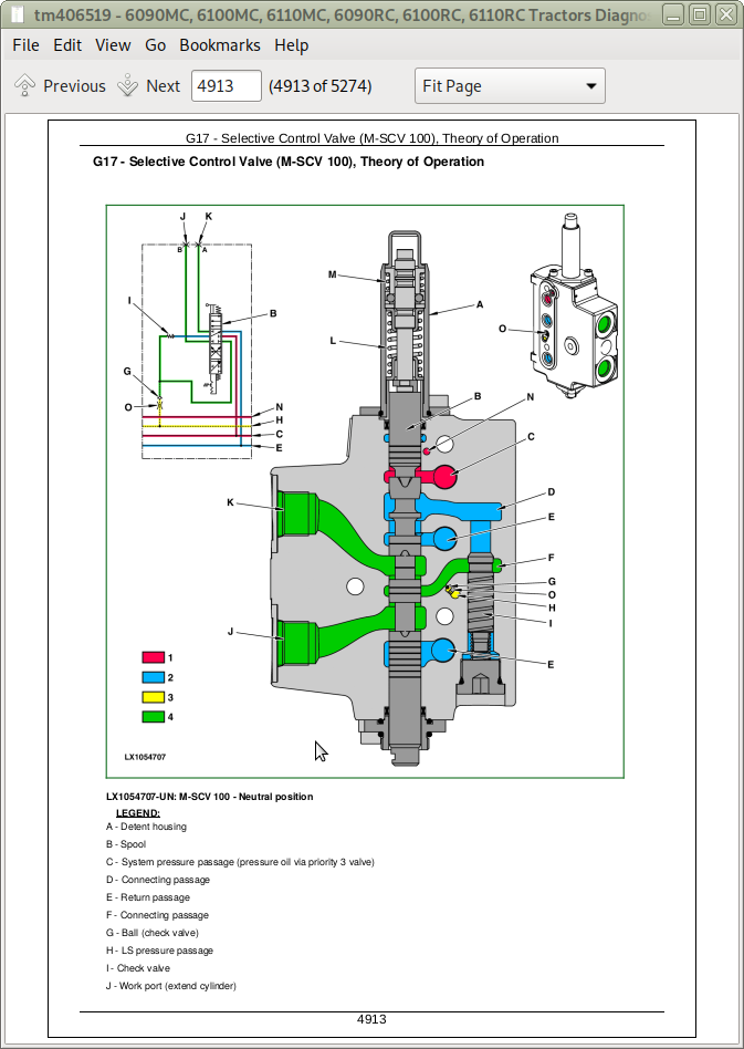
Selective Control Valves (SCVs) - Theory of Operation
Independent Control Valves (ICVs) - Theory of Operation
Hydraulic System - Schematics
Hydraulic System - Tests and Adjustments
Hydraulic System - Component Information
Hydraulic System - Component Information
Machine-Specific Systems
Machine-Specific Systems - Operational Checks
Machine-Specific Systems - Tests and Adjustments
Suspension Systems
Suspension Systems - Operational Checks
Suspended Front-Wheel Drive Axle - Theory of Operation
Suspended Front-Wheel Drive Axle - Schematics
Suspended Front-Wheel Drive Axle - Tests and Adjustments
Suspension Systems - Component Information
Suspended Front-Wheel Drive Axle - Component Information
Operator's Cab
Operator's Cab - Operational Checks
Operator's Cab - Theory of Operation
Operator's Cab - Tests and Adjustments
Operator's Cab - Component Information
Air Conditioning System - Component Information
Special Tools
General Information
tm406519 - 6090MC, 6100MC, 6110MC, 6090RC, 6100RC, 6110RC Tractors Diagnosis -: (Worldwide Edition)
Table of Contents
Foreword
Section 210: General Information
Group 05: Safety Measures
General Information - Safety - Summary of References
Recognize Safety Information
Understand Signal Words
Follow Safety Instructions
Prevent Machine Runaway
Operating the Tractor Safely
Operating the Loader Tractor Safely
Passenger Seat
Use Safety Lights and Devices
Towing Trailers/Implements Safely (Mass)
Use Caution On Slopes and Uneven Terrain
Freeing a Mired Machine
Avoid Backover Accidents
Handle Fluids Safely—Avoid Fires
Handling Batteries Safely
Prepare for Emergencies
Avoid High-Pressure Fluids
Service Cooling System Safely
Remove Paint Before Welding or Heating
Avoid Heating Near Pressurized Fluid Lines
Work In Ventilated Area
Avoid Contact with Agricultural Chemicals
Handle Agricultural Chemicals Safely
Stay Clear of Rotating Drivelines
Wear Protective Clothing
Protect Against Noise
Practice Safe Maintenance
Avoid Hot Exhaust
Exhaust Filter Cleaning
Clean Exhaust Filter Safely
Read Operator Manuals for ISOBUS Implements
Use Steps and Handholds Correctly
Use Seat Belt Properly
Park Machine Safely
Use Proper Lifting Equipment
Construct Dealer-Made Tools Safely
Support Machine Properly
Work in Clean Area
Illuminate Work Area Safely
Service Machines Safely
Service Accumulator Systems Safely
Service Tires Safely
Use Proper Tools
Service Front-Wheel Drive Tractor Safely
Avoid Eye Contact With Radar
Keep ROPS Installed Properly
Replace Safety Signs
Replace Safety Signs
Dispose of Waste Properly
Live With Safety
Safety Measures on Electronic Control Units
Servicing Electronic Control Units
Welding Near Electronic Control Units
Keep Electronic Control Unit Connectors Clean
Safety Instructions for Replacing a Halogen Bulb
Safety Instructions for Replacing Xenon (HID) Bulbs and Ballast Units
Group 10: General References
General Information - General References, Summary of References
Trademarks
Hydraulic Designators
Electrical Designators
General Information - Inch Bolt and Cap Screws, Torque Values
General Information - Metric Bolt and Cap Screws, Torque Values
General Information - Hydraulic System Inch Fittings, Torque Values
General Information - Hydraulic System Metric Fittings, Torque Values
General Information - Electrical System, Component Identification Table
General Information - Electrical System, How to Read a Diagnostic Schematic
General Information - Electrical System, Lead Numbers and Color Codes
General Information - Electrical System, Symbols in Schematic, Wiring and Harness Diagrams
General Information - Electrical System, Check the Connectors
General Information - Electrical System, Approach to Tabular Diagnostic Procedures
General Information - Electrical System, Troubleshooting Unsolved Problems
General Information - Electrical System, Worksheet for Circuit/Harness Test
General Information - Electrical System, Visual Check
General - Electrical System, Faults and Circuit Tests
General - Electrical System, Test for Open Circuit under Load
General Information - Electrical System, Seven-Step Test Procedure
General Information - Hydraulic System, Symbols in Circuit Diagrams
General - Regions and Country Versions
Section 211: Diagnostic Trouble Codes
Group AIC: AIC Control Software
AIC 000158.03 - Supply Voltage (ELX) Too High
AIC 000158.04 - Supply Voltage (ELX) Too Low
AIC 000168.03 - Supply Voltage Too High
AIC 000168.04 - Supply Voltage Too Low
AIC 000628.02 - Control Software Internal Fault
AIC 000628.12 - Control Software Internal Fault
AIC 000629.12 - Control Software Internal Fault
AIC 003509.03 - Sensor Supply Voltage #1 Too High
AIC 003509.04 - Sensor Supply Voltage #1 Too Low
AIC 003509.06 - Sensor Supply Voltage #1, Current Too High
AIC 003510.03 - Sensor Supply Voltage #2 Too High