
John Deere L330 L330C L340 L340C Large Square Baler Workshop Repair Service Manual PDF TM133219 - MJODTM133219.zip
A full-coverage diagnostic and repair guide, complete with electrical schematics, for the John Deere Hay and Forage Large Square Balers L330, L330C, L340, and L340C — packed with the technical detail needed to maintain, troubleshoot, and service these machines the way professional technicians do.
Contained within the John Deere Hay and Forage Large Square Balers L330, L330C, L340, and L340C workshop Diagnosis Operation Test Service Repair Manual you will find:
* Numbered table of contents easy to use so that you can find the information you need fast.
* Detailed sub-steps expand on repair procedure information
* Numbered instructions guide you through every repair procedure step by step.
* Troubleshooting and electrical service procedures are combined with detailed wiring diagrams for ease of use.
* Notes, cautions and warnings throughout each chapter pinpoint critical information.
* Bold figure number help you quickly match illustrations with instructions.
* Detailed illustrations, drawings and photos guide you through every procedure.
* Enlarged inset helps you identify and examine parts in detail.
tm133219 - John Deere Hay and Forage Large Square Balers Models L330, L330C, L340, L340C Diagnosis and Repair Technical Manual.pdf
PRODUCT DETAILS:
Total Pages: 1,847 pages
File Format: PDF (bookmarked, ToC, Searchable, Printable, high quality)
Language: English
MAIN SECTIONS
Foreword
General
Safety
Specifications
General Information
Lubrication
Drive Train
Diagnosing Malfunctions
Drive Train Protection
Gear Case Repair
Driveline Repair
Auto Grease System
General Information
Diagnosing Malfunctions
Auto Grease Repair
Divider Blocks
Electrical System
Connector Repair
Electrical Schematics
Tests and Adjustments
Control Units and Power Distribution
ISOBUS Monitor
Wire Harness Routing
Sensors
Hydraulic System
General Information
Diagnosing Malfunctions
Hydraulic Functional Schematics
Valves, Pumps and Motors
Cylinders
Accumulators
Miscellaneous
Pickup and Rotor
General Information
Diagnosing Malfunctions
Pickup Repair
Rotor Repair
Precutter
General Information
Diagnosing Malfunctions
3x3 Pickup Precutter
3x4 Pickup Precutter
Feeding System
General Information
Diagnosing Malfunctions
Adjust Feeding System
Feeding System Repair
Bale Chamber
General Information
Diagnosing Malfunctions
Plunger
Tension Panels and Channels
Bale Chamber
Last Bale Ejection
Bale Chute
Tying System
General Information
Diagnosing Malfunctions
Knotter Repair
Knotter System Repair
Needle Repair
Replacing Brakes
Knotter Trip Mechanism
Adjusting Knotter
Adjusting Needles
Knotter Fan
Brakes and Suspension
General Information
Diagnosing Malfunctions
Hydraulic Brake System
Brake Components
Wheels, Axles, and Steering
Body Repair
Front Shield and Gull Wings Doors
Twine Boxes and Work Platforms
Fiberglass Repair
Dealer Fabricated Tools
Dealer Fabricated Tools
Electrical Component Information
Electrical Assemblies
Sensors
Lights
Fuses
Motors
Interconnects and Ground Points
Electronically Actuated Mechanical Devices
Hydraulic Component Information
Accumulator
Sensor or Gauge
Cylinder, Actuator, or Piston
Filter
Valve Block, Assembly, or Gear Case
Cooler
Motor
Orifice
Pump
Reservoir or Tank
Valve
Solenoid Valve
tm133219 - Large Square Balers
Table of Contents
Foreword
Section 10: General
Group 05: Safety
Recognize Safety Information
Understand Signal Words
Follow Safety Instructions
Handle Fluids Safely—Avoid Fires
Prepare for Emergencies
Park Machine Safely
Support Machine Properly
Wear Protective Clothing
Work in Clean Area
Service Machines Safely
Work In Ventilated Area
Illuminate Work Area Safely
Replace Safety Signs
Use Proper Lifting Equipment
Avoid High-Pressure Fluids
Wait Before Opening High-Pressure Fuel System
Maximum Hydraulic Operating Pressure
Service Accumulator Systems Safely
Remove Paint Before Welding or Heating
Avoid Heating Near Pressurized Fluid Lines
Follow Tire Recommendations
Service Tires Safely
Avoid Harmful Asbestos Dust
Practice Safe Maintenance
Use Proper Tools
Construct Dealer-Made Tools Safely
Decommissioning — Proper Recycling and Disposal of Fluids and Components
Servicing Electronic Control Units
Welding Near Electronic Control Units
Keep Electronic Control Unit Connectors Clean
Precautions for Welding
Protect Against High Pressure Spray
Live With Safety
Group 10: Specifications
Large Square Baler Specifications
Unified Inch Bolt and Screw Torque Values
Metric Bolt and Screw Torque Values
Metric Face Seal and O-Ring Stud End Fitting Torque Chart—Standard Pressures
SAE Face Seal and O-Ring Stud End Fitting Torque Chart—Standard Pressures
Face Seal Fittings Assembly and Installation—All Pressure Applications
Service Recommendations For 37° Flare and 30° Cone Seat Connectors
Tighten Bearing Locking Collars
Prevent Hydraulic System Contamination
Check Oil Lines and Fittings
Group 15: General Information
Specifications
Machine Description
Baler Serial Number Plate
Select Tractor PTO Speed
Adjust Baler Hitch
Adjust Tractor Drawbar
Transporting Large Square Baler Safely
Group 20: Lubrication
Other Material
Specifications
Lubricate and Maintain Machine Safely
Observe Service Intervals
Grease
Gear Oil
Use of Gear Oil
Hydraulic Oil
Use of Hydraulic Oil
Section 20: Drive Train
Group 10: Diagnosing Malfunctions
Diagnosing Driveline
Diagnosing Gear Case
Diagnosing Drive Chain
Group 15: Drive Train Protection
Other Material
Specifications
Remove and Install Friction and Automatic Overload Clutch
Friction and Automatic Overload Clutch Exploded View
Replace Flywheel Shear Bolt
Disassemble and Assemble Flywheel Shear Bolt Assembly
Friction Clutch Adjustment
Remove and Install Feeder Fork Drive Slip Clutch
Remove and Install Rotor Clutch
Remove and Install Pickup Clutch
Replace Needle Frame Drive Shear Bolts
Group 20: Gear Case Repair
Essential or Recommended Tools
Other Material
Specifications
Remove and Install Main Drive Gear Case
Remove and Install Feeder Fork Drive Gear Case
Disassemble and Assemble Feeder Fork Drive Gear Case
Feeder Fork Drive System Exploded View
Feeder Fork Gear Case Exploded View
Remove and Install Upper Knotter Gear Case
Disassemble and Assemble Upper Knotter Gear Case
Upper Knotter Gear Case Exploded View
Remove and Install Knotter Clutch Drive Lug
Remove and Install Knotter Clutch External Stop
Remove and Install 3x4 Lower Knotter Gear Case
Remove and Install 3x3 Lower Knotter Gear Case
Disassemble and Assemble Lower Knotter Gear Case
Lower Knotter Gear Case Exploded View
Group 30: Driveline Repair
Essential or Recommended Tools
Other Material
Specifications
Remove and Install PTO Driveline Pedestal Bearings
Remove and Install Flywheel
Remove and Install Flywheel Bearings
Remove and Install Main Drive Gear Case Drive Arms
Replace Flywheel Brake Belt
Remove and Install Rear Drive Shaft Bearing
Remove and Install Swinging Shaft
Remove and Install Swinging Shaft Roller Arms
3x4 Swinging Shaft Exploded View
Section 30: Auto Grease System
Group 05: General Information
Other Material
Automatic Grease System
Group 10: Diagnosing Malfunctions
Grease System Difficulties
Group 15: Auto Grease Repair
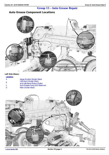
Auto Grease Component Locations
Auto-Grease Line Routing
Automatic Grease System Schematics
Remove and Install Pump Piston
Remove and Install Grease Pump Assembly
Priming Grease System
Bleeding Automatic Grease System Pump
Auto Grease System Blockage
Remove and Install Knotter Grease Line
Repair Low and High Pressure Grease Lines
Group 20: Divider Blocks
Other Material
Remove and Install Knotter Divider Blocks
Remove and Install Divider Blocks
Section 40: Electrical System
Group 05: Connector Repair
Essential or Recommended Tools
Other Material
Use Electrical Insulating Compound
Using High-Pressure Washers
Electrical System Visual Inspection
Basic Electrical Component Handling / Precautions for Vehicles Equipped with Computer Controlled Systems
Electrical Connector / Wiring Harness Handling and Repair
Installation of Repair Wire Assembly (RWA)
Repair Procedure R-A
Repair Procedure R-C
Repair Procedure R-D
Repair Procedure R-E
Repair Procedure R-F
Repair Procedure R-G
Repair Procedure R-I
Repair Procedure R-J
Repair Procedure R-AE
Repair Procedure R-AJ
Group 15: Electrical Schematics
Auto Greasing Electrical Schematic
Bale Accumulator (Optional) Electrical Schematic
Bale Quality Electrical Schematic
Drivetrain Electrical Schematic
Feeding System Electrical Schematic
ISOBUS - Power Supply Electrical Schematic
LED Work Lights (Optional) Electrical Schematic
Lighting Electrical Schematic
Tying System Electrical Schematic
ISOBUS Battery Wiring Schematic
ISOBUS Cab Wiring Schematic
Group 20: Tests and Adjustments
Service Equipment and Tools
Diagnostic Screens—ISOBUS Display
Sensors—Test Input Screens
Sensors—Test Output Screens
Calibrate Slack Arm Sensors—ISOBUS Display
Baler Settings—ISOBUS Display
Next VT Function
Advanced and Factory Settings—ISOBUS Display
Common Circuit Test
Welding on Baler Equipped with ISOBUS Display and Electrical Control Unit (ECU)
Group 25: Control Units and Power Distribution
Remove and Install Electronic Control Unit (ECU)
Programming Control Units—Service ADVISOR (Recommended)
Group 30: ISOBUS Monitor
Home Screen Layout
Remove and Install Display