

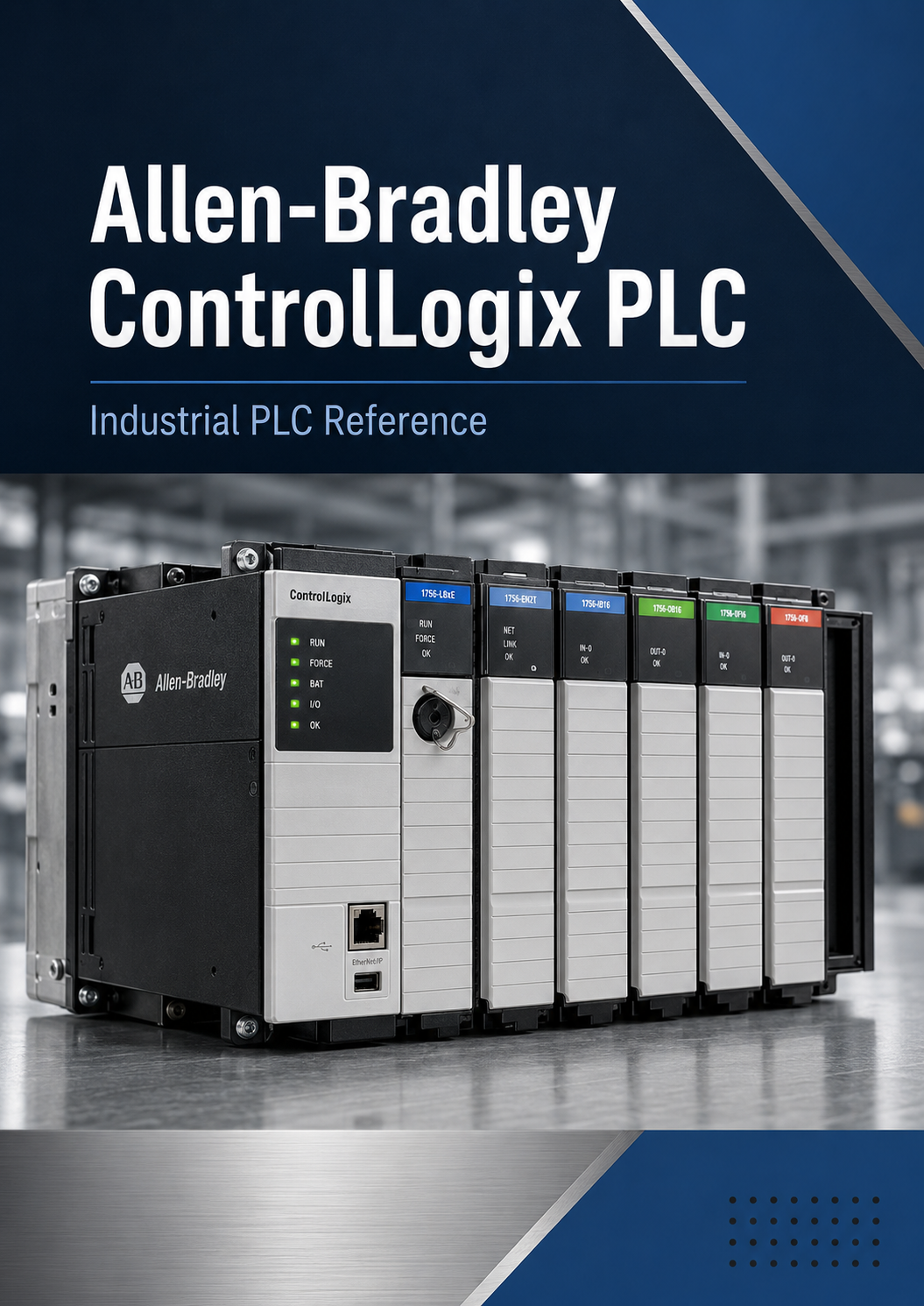
Allen Bradley PLC I/O Troubleshooting Guide
Allen-Bradley PLC I/O Troubleshooting Guide
Troubleshoot PLC-controlled equipment even when you do not have access to the ladder logic.
The Shepherd Manuals Allen-Bradley PLC I/O Troubleshooting Guide is a practical field reference for industrial electricians, maintenance technicians, apprentices, and multi-craft personnel working with Allen-Bradley PLC-controlled machinery.
Instead of teaching PLC programming, this guide focuses on the electrical troubleshooting work that can be performed directly at the machine, I/O modules, terminal blocks, sensors, relays, contactors, solenoids, motors, and other field devices.
The central troubleshooting method is simple:
NO INPUT:
Field Device → Power → Signal → Wiring → PLC Terminal → Input Channel → Controls
NO OUTPUT:
PLC Output Status → Output Terminal → Wiring → Relay/Contactor → Field Device → Load
The guide helps the technician determine where the expected electrical condition stops being true and whether the problem is in the field wiring, I/O circuit, PLC hardware, output device, motor circuit, actuator—or beyond the electrician's troubleshooting boundary inside the PLC program.
Topics Include
- Allen-Bradley PLC I/O troubleshooting
- ControlLogix and Compact 5000 field diagnostics
- Digital inputs and outputs
- 24 VDC PNP and NPN sensors
- Dry-contact inputs
- AC input circuits
- Relay, transistor, and AC output circuits
- PLC module and channel indicators
- Module power versus field power
- Shared commons and output power groups
- 1756 removable terminal block troubleshooting
- 5069 MOD and SA power concepts
- 4–20 mA analog inputs
- 0–10 V analog signals
- Analog outputs
- RTDs and thermocouples
- Motor starter troubleshooting
- Interposing relays and contactors
- Solenoid valves and actuators
- VFD hardwired command troubleshooting
- Open circuits, shorts, blown fuses, and loss of field power
- Practical meter test points
- Expected voltage and current readings
- Detailed troubleshooting flowcharts
- Probable-cause tables
- Worked field troubleshooting examples
- When to stop electrical troubleshooting and call controls
Designed for the Plant Floor
Detailed test-point diagrams show the technician where to place the meter leads, what reading should be expected, and what the result indicates.
The manual emphasizes an important principle:
A PLC LED is a diagnostic clue—not proof that the complete field circuit is operating correctly.
The electrician learns to verify the electrical condition at the actual terminal and follow the circuit systematically toward the source of the fault.
Ideal For
- Industrial electricians
- Maintenance electricians
- Electrical apprentices
- Maintenance technicians
- Multi-craft technicians
- Industrial maintenance departments
- Apprenticeship programs
- Technical colleges
- Manufacturing facilities
- Electricians transitioning into industrial maintenance
No Ladder Program Required
This guide was developed specifically for technicians who may not have Studio 5000 access, programming privileges, or authorization to troubleshoot PLC logic.
It teaches the technician how to thoroughly troubleshoot the electrical and field-device side of an Allen-Bradley PLC system and recognize when the field circuit has been proven and controls support is required.
Shepherd Manuals
Practical Industrial Training for the Apprentice, Technician, Electrician, and Engineer.