
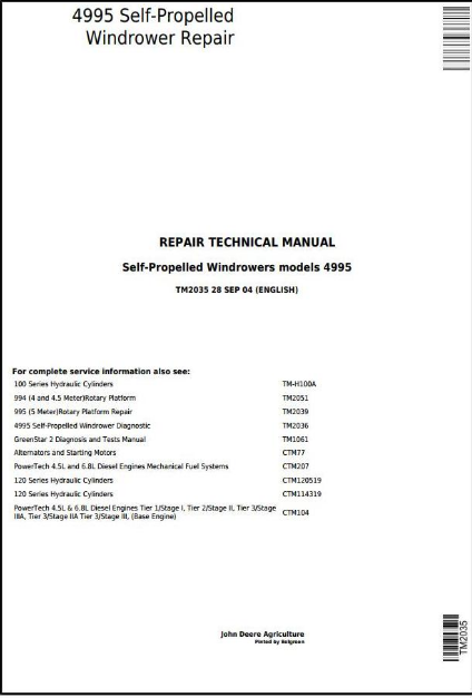
John Deere 4995 Self-Propelled Windrower Hay and Forage Workshop Repair Service Manual TM2035 PDF Download - MJODTM2035.zip
John Deere Self-Propelled Windrowers Hay and Forage 4995 Repair Service Technical Manual (TM2035)
The TM2035 is the official repair technical manual, delivered as a PDF, covering the John Deere 4995 Self-Propelled Windrowers in the Hay and Forage lineup.
Complete service repair manual for John Deere Self-Propelled Windrowers Hay and Forage Models 4995 , with all the shop information to maintain, repair, service like professional mechanics.
John Deere 4995 Self-Propelled Windrowers Hay & Forage workshop service repair manual includes:
* Numbered table of contents easy to use so that you can find the information you need fast.
* Detailed sub-steps expand on repair procedure information
* Numbered instructions guide you through every repair procedure step by step.
* Notes, cautions and warnings throughout each chapter pinpoint critical information.
* Bold figure number help you quickly match illustrations with instructions.
* Detailed illustrations, drawings and photos guide you through every procedure.
* Enlarged inset helps you identify and examine parts in detail.
Total Pages: 1,102 pages
File Format: PDF (bookmarked, ToC, Searchable, Printable, high quality)
Language: English
MAIN SECTIONS
Foreword
Service Technician Response
General
Safety
Specifications
Fuel, Coolant and Lubricants
Engine
Engine
Cooling System
Fuel and Air Systems
Air Intake and Exhaust
Diesel Fuel System
Electrical
Battery
Starter
Alternator
Engine Electrical Components
Lighting and Accessory Components
Gauges and Monitors
Platform and Ground Speed Controls
Cab Heat and A/C Electrical Components
Connector Repair
Power Train
Hydrostatic System Flushing and Start-Up
Pump Drive Gear Case
Circulating Pump and Oil Cooler
Ground Drive Pumps
Ground Drive Motor
Final Drive (Serial No. -310400)
Final Drive With Internal Park Brake (Serial No. 310401-)
Ground Drive Linkage
Steering and Brakes
Steering System
Brakes (Serial No. -310400)
Hydraulic System
Component Location
Auxiliary-Charge Pump
Platform Drive Pump
Platform Drive Motor
Main Hydraulic Control Valve
Hydraulic Cylinders
Miscellaneous
Miscellaneous
Rear Axle
Drive Wheels
Lift Arm
Operator Station
Air Conditioning Service
Air Conditioning Repair
Heater Controls
Cab
Dealer Fabricated Tools
Dealer Fabricated Tools
tm2035 - 4995 Self-Propelled Windrower
Table of Contents
Foreword
Service Technician Response
Section 10: General
Group 05: Safety
Recognize Safety Information
Understand Signal Words
Handle Fluids Safely—Avoid Fires
Handling Batteries Safely
Prevent Battery Explosions
Prepare for Emergencies
Prevent Acid Burns
Avoid High-Pressure Fluids
Service Accumulator Systems Safely
Park Windrower Safely
Stay Clear of Rotating Driveline
Support Machine Properly
Wear Protective Clothing
Work in Clean Area
Service Machines Safely
Work In Ventilated Area
Illuminate Work Area Safely
Replace Safety Signs
Use Proper Lifting Equipment
Remove Paint Before Welding or Heating
Avoid Heating Near Pressurized Fluid Lines
Service Tires Safely
Avoid Harmful Asbestos Dust
Practice Safe Maintenance
Use Proper Tools
Construct Dealer-Made Tools Safely
Use Adequate Service Facilities
Dispose of Waste Properly
Practice Safe Service Procedures
Live With Safety
Group 10: Specifications
4995 Self-Propelled Windrower Specifications Specifications and design subject to change without notice.
Dimensions
Metric Bolt and Screw Torque Values
Unified Inch Bolt and Screw Torque Values
Face Seal Fittings Assembly and Installation—All Pressure Applications
SAE Face Seal Fitting Torque Chart—Standard Pressure Applications
SAE Face Seal Fitting Torque Chart—High Pressure Applications
Four Bolt Flange Fittings Assembly and Installation—All Pressure Applications
SAE Four Bolt Flange Cap Screw Torque Values—High Pressure Applications
Service Recommendations For 37° Flare and 30° Cone Seat Connectors
Service Recommendations For Snap-To-Connect Fittings
Product Identification Number Plate
Windrower Product Identification Number Plate Location
Engine Serial Number
Fuel Injection Pump Serial Number
Cab Serial Number
Group 15: Fuel, Coolant and Lubricants
Diesel Fuel
Biodiesel Fuel
Diesel Fuel Storage
Lubricity of Diesel Fuel
Diesel Engine Coolant
Supplemental Coolant Additives
Operating in Warm Temperature Climates
Additional Information About Diesel Engine Coolants and John Deere LIQUID COOLANT CONDITIONER
Testing Diesel Engine Coolant
Diesel Engine Oil
Diesel Engine Break-In Oil
Hydraulic Pump Drive Gear Case, Hydrostatic Drive and Main Hydraulic Systems Oil
Final Drive Oil
Grease
Alternative and Synthetic Lubricants
Lubricant Storage
Section 20: Engine
Group 05: Engine
John Deere Engine Repair—Use CTM104
Essential or Recommended Tools
Service Equipment and Tools
Specifications
Remove and Install Engine
Checking Vibration Damper
Replace Vibration Damper
Replace Engine Mount Isolators
Remove and Install Serpentine Belt
Group 10: Cooling System
Engine Water Pump Repair—Use CTM104
Essential or Recommended Tools
Other Material
Specifications
Inspect Cooling System
Remove And Install Radiator
Disassemble, Inspect and Assemble Radiator Assembly
Fill Radiator
Winterize Cooling System
Flush Out Cooling System
Section 30: Fuel and Air Systems
Group 05: Air Intake and Exhaust
Turbocharger Repair—Use CTM104
Cleaning Bowl-Type Air Precleaner
Cleaning Precleaner Screen
Cleaning Filter Housing Air Precleaner
Remove and Install Air Filters
Clean and Inspect Primary Air Filter
Remove and Install Air Precleaner and Intake Tube
Remove and Install Exhaust Tube
Group 10: Diesel Fuel System
Injection Pump, Nozzle, and Governor Repair—Use CTM207
Specifications
Shut Off Fuel Supply
Drain Fuel Tank
Remove and Install Fuel Tank
Do Not Modify Fuel System
Drain Water From Fuel Filter
Bleed Fuel Filter
Change Fuel Filter
Bleed Fuel Injection Pump
Bleed Fuel Lines to Injectors
Check and Set Engine Speed
Section 40: Electrical
Group 05: Battery
Specifications
Remove and Install Battery
Connecting Booster Battery
Charging Battery
Checking Specific Gravity
Group 10: Starter
Starter Repair—Use CTM77
Specifications
Remove and Install Starter Motor
Group 15: Alternator
Alternator Repair—Use CTM77
Remove and Install Alternator
Group 20: Engine Electrical Components
Other Material
Replace Fuel Level Sensor
Replace Air Restriction Switch
Replace Engine Coolant Temperature Switch
Replace Engine Coolant Temperature Sensor
Replace Engine Oil Pressure Switch
Replace Engine Speed Sensor
Replace Throttle Motor
Disassemble and Inspect Throttle Motor
Remove Rotating Wand Motor
Rotating Wand Motor—Exploded View
Install Rotating Wand Motor
Group 25: Lighting and Accessory Components
Specifications
Halogen Bulb Safety Guidelines
Replace and Adjust Cab Headlight Bulb
Remove and Install High Intensity Discharge (HID-Xenon) Lights (Optional) (S. N. 320001—)
Remove and Install High Intensity Discharge (HID-Xenon) Ballasts (S. N. 320001—)
Replace Flood Light Bulb
Replace Rear Warning, Tail, and Side Marker Light Bulbs
Replace Turn Signal Indicator Bulb
Replace Dome and Console Light Bulb
Replace Key Switch
Replace Light Switches and Wiper Switch
Replace Turn Signal Switch
Replace Horn Switch
Replace Horn
Replace Overhead Console Horn
Replace Seat Switch
Replace Wiper Motor
Adjust Windshield Wiper Park Position—Short Arm
Adjust Windshield Wiper—Long Arm (Optional)
Replace Radio
Replace Radio Speaker
Remove and Install Radio Speaker (S. N. 320001—)
Replace Radio Antenna
Replace Radio Antenna (S. N. 320001—)
Mount Communications/CB Radio
Install FM Radio
Group 30: Gauges and Monitors
Replace Warning Panel or Light Bulbs
Replace Gauges or Gauge Light Bulbs
Replace Tachometer
Program Tachometer
Group 35: Platform and Ground Speed Controls
Essential or Recommended Tools
Service Equipment and Tools
Specifications
Replace Console Rocker Switches
Replace Hydro Lever Switch Module
Replace Hydro Lever Neutral Switch
Remove and Install Hydro Lever
Replace Platform Speed Control
Disassemble and Inspect Platform Speed Control
Replace Steering Neutral Start Switch
Replace Hydraulic Filter Restriction Switch
Replace Hydraulic Charge Pressure Switch
Replace Hydraulic Oil Temperature Switch
Replace Hydraulic Float Pressure Transducer
Replace Ground Speed Sensor
Adjust Ground Speed Sensor Magnetic Pickup
Replace Solenoid Coils
Group 40: Cab Heat and A/C Electrical Components
Other Material
Replace Blower Motor Control Switch
Replace Air Conditioning Temperature Control Switch
Replace Blower Motor
Replace Blower Motor Resistor
Replace Cab Pressurizer Motor
Replace Air Conditioning Thermostat
Replace Air Conditioning Low Pressure Switch
Replace Air Conditioning High Pressure Switch
Group 45: Connector Repair
Essential or Recommended Tools
Other Material
Electrical Connector Handling
Use Contact Cleaner and Di-electric Grease
Replace WEATHER PACK Connector
Install WEATHER PACK Terminal
Remove Connector Body from Blade Terminals
Replace METRI-PACK (Push Type) Connectors
Replace CPC, Large MATE-N-LOK and METRIMATE METRIMATE is a trademark of AMP Inc. Pin Type Connectors
Replace DEUTSCH Connectors
Install DEUTSCH Terminals
Section 50: Power Train
Group 05: Hydrostatic System Flushing and Start-Up
Specifications
Service Recommendations For Snap-To-Connect Fittings
Flush Hydrostatic Ground Drive System
Hydrostatic Ground Drive System Start-Up
Group 10: Pump Drive Gear Case
Essential or Recommended Tools
Service Equipment and Tools
Other Material
Remove and Install Pump Drive Gear Case
Disassemble and Inspect Pump Drive Gear Case
Assemble Pump Drive Gear Case
Group 15: Circulating Pump and Oil Cooler
Service Equipment and Tools
Other Material
Specifications
Flat Face O-Ring vs. Flare Hydraulic Fittings