
Komatsu PC240LL-10 Log Loader Road Builder Workshop Repair Service Manual PDF - MKMTSPC240LL.zip
Full service and repair guide featuring Electrical Wiring Diagrams for the Komatsu Log Loader Road Builder PC240LL-10, packed with the technical detail professionals rely on to service, troubleshoot, fix and rebuild the machine.
The workshop service repair manual for the Komatsu Log Loader Road Builder PC240LL-10 contains:
* Numbered table of contents easy to use so that you can find the information you need fast.
* Detailed sub-steps expand on repair procedure information
* Numbered instructions guide you through every repair procedure step by step.
* Troubleshooting and electrical service procedures are combined with detailed wiring diagrams for ease of use.
* Notes, cautions and warnings throughout each chapter pinpoint critical information.
* Bold figure number help you quickly match illustrations with instructions.
* Detailed illustrations, drawings and photos guide you through every procedure.
* Enlarged inset helps you identify and examine parts in detail.
PRODUCT DETAILS:
Total Pages: 345 pages
File Format: PDF (Internal Links, Bookmarked, Table of Contents, Searchable, Printable, high quality)
Language: English
CEBM028500 - Log Loader Road Builder PC240LL-10 Shop Manual.pdf
MAIN SECTIONS
CEBM028500 PC240LL-10 S/N A20601 & Up...1
CONTENTS...2
00 - FOREWORD ...3
SAFETY...3
Safety Notice...3
Important Safety Notice...3
General Precautions...3
Preparations For Work...4
Precautions During Work...4
GENERAL...7
HOW TO READ THE SHOP MANUAL...8
Volumes...8
Distribution And Updating...8
Filing Method...8
Revised Edition Mark...8
Revisions...8
Symbols...8
HOISTING INSTRUCTIONS...9
Hoisting...9
Making Signs...9
Precautions...9
Precautions for Sling Work...9
Precautions for Using Mobile Crane...10
Precautions for Using Overhead Hoist Crane...10
Selecting Wire Ropes...11
HANDLING ELECTRIC EQUIPMENT AND HYDRAULIC COMPONENTS...12
Points to Remember When Handling Electric Equipment...12
Points to Remember When Handling Hydraulic Equipment...23
PUSH PULL COUPLER...25
Type 1...25
Disconnection...25
Connection...25
Type 2...26
Disconnection...26
Connection...26
Type 3...27
Disconnection...27
Connection...27
EXPLANATION OF MAINTENANCE STANDARD TERMS...28
HANDLING OF FUEL SYSTEM DEVICES...29
HANDLING OF INTAKE SYSTEM PARTS...30
STANDARD TIGHTENING TORQUE...31
Bolts And Nuts...31
Tightening Torque Of Hose Nuts...32
Tightening Torque Of Split Flange Bolts...32
Tightening Torque For Flared Nuts...32
Tightening Torques for Split Flanged Bolts...33
Tightening Torques For O-ring Boss Piping Joints...33
Table Of Tightening Torques For O-ring Boss Plugs...33
Tightening Torque For Hoses (Taper Seal Type And Face Seal Type)...34
Tightening Torque For Face Seal Joints...34
For 102, 107, and 114 Engine Series (Bolts and Nuts)...34
For 102, 107, and 114 Engine Series (Eye Joints)...35
For 102, 107, and 114 Engine Series (Taper Screws)...35
ELECTRIC WIRE CODE...36
Classification By Thickness...36
Classification By Color And Code...36
How To Read Electric Wire Code...37
PRECAUTIONS FOR OPERATIONS...40
Precautions when Carrying Out Removal Work...40
Precautions when Carrying Out Installation Work...41
Precautions when Completing the Operation...42
CONVERSION TABLES...43
Method Of Using The Conversion Table...43
COATING MATERIALS...49
LIST OF ABBREVIATIONS...52
List of Abbreviations Used in the Shop Manual...52
List of Abbreviations Used in the Circuit Diagrams...56
01 - GENERAL...57
SPECIFICATIONS...58
Dimension Drawings...58
Road Builder...58
Log Loader...58
Dimensions...59
Working Ranges...61
Road Builder...61
Log Loader...62
Engine...63
Undercarriage...63
Hydraulic System...64
Road Builder...64
Log Loader...65
WEIGHT TABLE...66
FUEL, COOLANT AND LUBRICANTS...68
Lubrication Chart...70
10 - STRUCTURE AND FUNCTION...71
ENGINE AND COOLING SYSTEM...74
Engine Related Parts...74
Radiator, Oil Cooler, Aftercooler, and Fuel Cooler...76
POWER TRAIN...78
Power Train...78
Swing Machinery...80
Swing Circle...82
Final Drive...84
UNDERCARRIAGE AND FRAME...86
Track Frame and Idler Cushion...86
HYDRAULIC SYSTEM...88
Hydraulic Equipment Layout...88
Valve Control...90
Hydraulic Tank...92
Oil Filler Cap...93
CLSS...94
Structure of CLSS...94
Basic Principle...95
Main Pump...98
Operation...102
LS Valve...104
PC Valve...110
LS(PC)-EPC Valve...117
Control Valve...120
Functions and Operation by Valve...132
Hydraulic Circuit Diagram and Name of Valves...132
Unload Valve...135
Introduction of LS Pressure...136
LS By-Pass Plug...137
Pressure Compensation Valve...138
Shuttle Valve In Pressure Compensation Valve...141
Boom Regeneration Circuit...143
Arm Regeneration Circuit...145
Merge-Divider Valve...147
LS Selector Valve...150
Self-Pressure Reducing Valve...151
Travel Junction Valve...154
Travel PPC Shuttle Valve...157
Boom Hydraulic Drift Prevention Valve...159
Arm Hydraulic Drift Prevention Valve (Road Builder)...162
Arm Drift Prevention Valve (Log Loader)...165
Operation...166
Suction Safety Valve For Drift Prevention Valve...168
Arm Quick Return Valve...169
Variable Back Pressure Valve...171
Main Relief Valve...173
Swing Motor...174
Swing Holding Brake...176
Relief Valve...178
Swing 2-Stage Relief Valve...180
Swing Motor Reverse Prevention Valve...181
Travel Motor...184
Operation of Travel Motor...187
Operation of Parking Brake...189
Brake Valve...190
Counterbalance Valve...191
Suction Safety Valve...192
PPC Valve...196
Work Equipment and Swing PPC Valve...196
Travel PPC Valve...201
Solenoid Valve...206
Attachment Solenoid Valve...209
Center Swivel Joint...211
Accumulator...213
PPC Accumulator...213
WORK EQUIPMENT...214
Road Builder...214
Log Loader...215
Work Equipment Shim...216
Bucket Play Adjustment Shim (Road Builder)...216
CAB AND ITS ATTACHMENTS...217
ELECTRICAL SYSTEM...219
Electrical Control System...219
Machine Control System Diagram...219
Engine Control Function...221
Engine and Pump Combined Control Function...223
Pump and Valve Control Function...229
One-Touch Power Maximizing Function...231
Auto-Deceleration Function...233
Engine Automatic Warm-Up Function...235
Overheat Prevention Function...237
Turbocharger Protection Function...238
Swing Control Function...239
Quick Warm-Up Function...243
Swing 2-Stage Relief Function...243
Travel Control Function...244
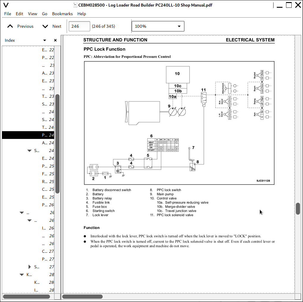
PPC Lock Function...246
Attachment Flow Control Function...247
System Component Part...249
Engine Controller...249
Pump Controller...253
Fuel Control Dial...256
Resister for PC-EPC valve...257
CAN Terminating Resistor...258
Engine Oil Pressure Switch...259
PPC Oil Pressure Switch...260
MACHINE MONITOR SYSTEM...261
Machine Monitor...263
Input and Output Signals...264
Display...266
Gauges...268
Caution Monitor...270
Pilot Monitor...273
Switches...275
Guidance ICON and Function Switch...277
Operator Mode Function...280
Service Mode Function...282
KOMTRAX SYSTEM...283
KOMTRAX terminal...284
Input and Output Signals...285
SENSORS...287
Ambient Pressure Sensor...287
Charge (Boost) Pressure and Temperature Sensor...288
Coolant Temperature Sensor...289
Ne (Crankshaft) Speed Sensor...289
Bkup (Camshaft) Speed Sensor...290
Common Rail Pressure Sensor...290
Exhaust Manifold Pressure Sensor...291
EGR Orifice Temperature Sensor...291
EGR Valve Lift Sensor...292
Turbo Speed Sensor...293
KVGT Position Sensor...294
Mass Air Flow and Temperature Sensor...295
KDPF Differential Pressure and Outlet Pressure Sensor...295
KDOC Inlet Temperature Sensor...296
KDOC Outlet Temperature Sensor...296
KDPF Outlet Temperature Sensor...297
Crankcase Pressure Sensor...297
Engine Oil Level Sensor...298
Fuel Level Sensor...299
Coolant Level Sensor...300
Hydraulic Oil Temperature Sensor...300
Front Pump Oil Pressure Sensor...301
Rear Pump Oil Pressure Sensor...302
PPC Oil Pressure Sensor...303
Air Cleaner Clogging Sensor...304
Front Pump Swash Plate Sensor...305
Rear Pump Swash Plate Sensor...307
Water-In-Fuel Sensor...309
20 - STANDARD VALUE TABLES...311
STANDARD SERVICE VALUE TABLES...312
Standard Value Table for Engine Related Parts...312
Standard Value Table for Chassis Related Parts...314
Engine Speed...314
Control Valve Spool Stroke...314
Control Lever Stroke...315
Operating Effort of Control Lever and Pedal...315
Hydraulic Pressure...316
Swing...317
Travel...318
Work Equipment...319
Performance in Combined Operation...321
Pump Swash Plate Sensor...321
Hydraulic Pump...322
Posture of Machine for Measuring Performance and Measurement Procedure...323
Control Valve: Spool Stroke...323
Swing 1: Overrun When Stopping Swing, Time Taken to Start Swing, Time Taken to Swing...323
Swing 2: Hydraulic Drift of Swing...323
Travel 1: Travel Speed, Idle Running (Without Load)...324
Travel 2: Travel Speed (Actual Run), Travel Deviation...324
Travel 3: Travel Deviation...325
Travel 4: Hydraulic Drift of Travel...325
Work Equipment 1: Hydraulic Drift of Work Equipment...326
Work Equipment 2: Boom Speed...326
Work Equipment 3: Arm Speed...326
Work Equipment 4: Bucket Speed/Heel Speed...327
Work Equipment 5: Boom Time Lag...327
Work Equipment 6: Arm Time Lag...328
Work Equipment 7: Bucket Time Lag...328
90 - DIAGRAMS AND SCHEMATICS...329
HYDRAULIC SYSTEM...331
Symbols in Hydraulic Circuit Diagrams...331
Hydraulic Circuit Diagram (1/2)...332
Hydraulic Circuit Diagram (2/2)...333
ELECTRICAL SYSTEM...334
Symbols in Electrical Circuit Diagrams...334
Air Conditioner Electrical Circuit...335
Electrical Control System Diagram...336
Electrical Diagram (1/5)...337
Electrical Diagram (2/5)...338
Electrical Diagram (3/5)...339
Electrical Diagram (4/5)...340
Electrical Diagram (5/5)...341
Electrical Circuit Diagram - Log Loader Unique...342
Connector List and Stereogram...343
Chassis...343
Operator's Compartment...344
Engine Compartment...345