
John Deere 824 832 840 Trailed Crop Sprayer Diagnosis & Tests Workshop Manual PDF TM403419 - MJODTM403419.zip
Full Diagnostic & Testing guide featuring Electrical Wiring Diagrams for the John Deere 824, 832 and 840 Trailed Crop Sprayers, containing everything a workshop needs to service, troubleshoot, and maintain these machines at a professional level.
The Operation & Test service manual for the John Deere Trailed Crop Sprayers 824, 832 and 840 covers the following:
* Numbered table of contents easy to use so that you can find the information you need fast.
* Detailed sub-steps expand on repair procedure information
* Numbered instructions guide you through every repair procedure step by step.
* Troubleshooting and electrical service procedures are combined with detailed wiring diagrams for ease of use.
* Notes, cautions and warnings throughout each chapter pinpoint critical information.
* Bold figure number help you quickly match illustrations with instructions.
* Detailed illustrations, drawings and photos guide you through every procedure.
* Enlarged inset helps you identify and examine parts in detail.
TM403419 - John Deere Trailed Crop Sprayers Models 824, 832 and 840 Technical Manual (Diagnosis & Tests).PDF
Total Pages: 424 pages
File Format: PDF (bookmarked, ToC, Searchable, Printable, high quality)
Language: English
MAIN SECTIONS
Foreword
General Information
Safety
Electrical Diagnosis and Tests - 800se
Power Supply EL4
EL4 + EHS1 Connection 800SE
EL4+EHB1 Connection 800SE
EL4+EHS1 Connection 800SE V2
EL4+EHB1 Connection 800SE V2
LS for ELB1/EL4/EHC2 V1
Power Supply 3 pole Cobo connector
EL4 Connection V3 800SE
Update to B-motor
Electrical Diagnosis and Tests - 800i
Power Supply 3 Pole Cobo Connector
PCB Connection CAN box V3
Hydraulic Connection ISOBUS
Fuses
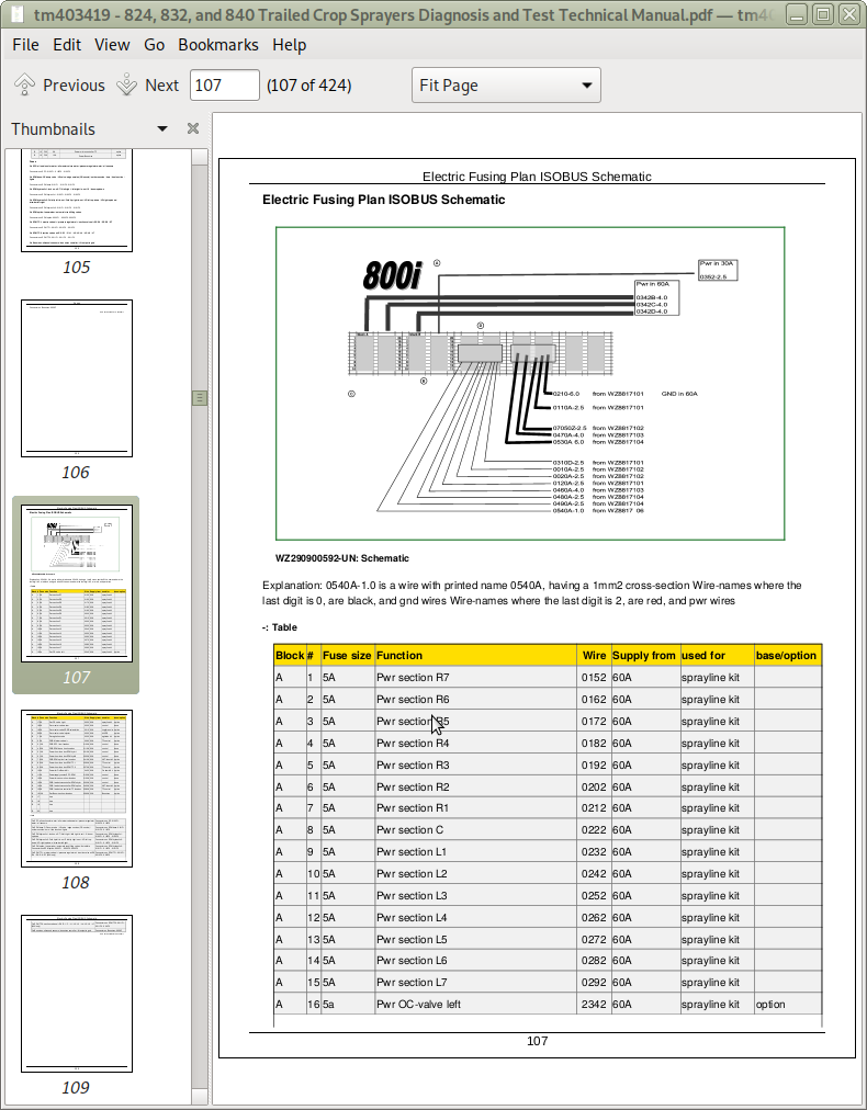
Electric Fusing Plan ISOBUS
Warning Screen Codes
Wiring Harness
Electrical Diagnosis and Tests - 800
Universal CAN Box Connector
Power Supply EL4
ELC1+EHC2 Connection
Universal CAN Box Connector V2
ELC1+EHC2 Connection Left 800
ELC1+EHC2 Connection Right 800
EL4+Tilt Connection 800
EL4+Tilt Preselect+Edge Nozzle Connector 800
Drawbars Sensor Connection 800
Lightning Connection 800
T-split cable CAN connection
ELC1+EHC2 Connection 800
EL4 Electrical Connection 800
EL4+EHS1 Connection 800
EHC2 Connection Right 800
EHC2 Connection Left 800
EL4+EHB2 Connection 800
Droplethose Bracket Connection
Universal CAN Box Connection V3
PCB Connection CAN Box V2
Modification of Drawbar Sensors on EHC2 Hydraulic
Modification of PCB Security on EHC2
Modification of Drawbar Sensors on EHB2
Modification of Drawbar Sensors on HySelect
Modification of Drawbar Sensors on EHC2 Electrical
EL4 Electrical Connection 800 V2
EL4+EHS1 Connection 800 V2
EL4+EHB2 Connection 800 V2
LS For ELB1/EL4/EHC2 V1
LS For EL4+EHC2 V1
Power Supply 3 Pole Cobo Connector
PCB Connection CAN Box V3
EHC2 Connection Left 800 V2
BoomTrac Connection
LS For GSD4+EHC2 V2.01
EL4 connection 800 V3
EL4 + Off Centre Nozzle Valves Connection 800
Update to B-motor
EL4 + Tankmatic Connection V2
Wiring Harness
Hydraulic Diagnostics - 800
SCV Lift/Symmetric Folding
SCV Lift/Asymmetric Folding
Electrohydraulic Lift/Symmetric Folding/Steering Drawbar
Electrohydraulic Lift/Assymmetric folding
Electrohydraulic Lift/Assymmetric Folding/Steering Drawbar
EH Lift/Symmetric Folding/Steering Drawbar/Variable Geometry
EH Lift/Asymmetric Folding/Steering Drawbar/Variable Geometry
HySelect Symmetric Folding/Steering Drawbar
HySelect Symmetric Folding
EHB2/EHC2 3 Part Folding Boom Tfi
EHS1 3 Part Folding Boom Tfi
EHB2/EHC2 2 Part Folding Boom No Variable Geometry
EHB2/EHC2 2 Part Folding Boom Variable Geometry
SCV Lift/Balance/Symmetric Folding
EHB2/EHC2 2 Part Folding Boom Tfi
Stand Alone Hydraulics 800
LS on EHB2/EHC2
Brakes 800
Hydraulic Diagnostics - 800SE
EHS1 800SE Hydraulics
EHB1 800SE Hydraulics
Stand Alone Hydraulics 800SE
Lift Balance Sequence Hydraulics 800SE
LS on EHB1, EHB2, EHC2 Hydraulics
Hydraulic Diagnostics - 800i
EHC2 3 Part Folding Boom Tfi Hydraulic
EHC2 2 Part Folding Boom Tfi Hydraulic
Stand Alone Hydraulic 800i
LS on EHC2 Hydraulic
Brake Hydraulics 800i
Plan Auto Dilute Hydraulics
tm403419 - 824, 832, and 840 Trailed Crop Sprayers Diagnosis and Test
Table of Contents
Foreword
Section 210: General Information
Group 05: Safety
Recognize Safety Information
Understand Signal Words
Perform Service Safely
Wait Before Opening High-Pressure Fuel System
Service Accumulator Systems Safely
Handle Fluids Safely—Avoid Fires
Prevent Battery Explosions
Prepare for Emergencies
Protect Against High Pressure Spray
Prevent Acid Burns
Wear Protective Clothing
Handle Agricultural Chemicals Safely
Service and Operate Chemical Sprayers Safely
Avoid Contact with Agricultural Chemicals
Clean Vehicle of Hazardous Pesticides
Support Machine Properly
Service Machines Safely
Practice Safe Maintenance
Avoid Harmful Asbestos Dust
Work In Ventilated Area
Work in Clean Area
Remove Paint Before Welding or Heating
Avoid Heating Near Pressurized Fluid Lines
Avoid High-Pressure Fluids
Service Tires Safely
Service Cooling System Safely
Illuminate Work Area Safely
Replace Safety Signs
Use Proper Lifting Equipment
Use Proper Tools
Construct Dealer-Made Tools Safely
Dispose of Waste Properly
Live With Safety
Section 240A: Electrical Diagnosis and Tests — 800se
Group 15A: Power Supply EL4
Power Supply EL4 Electrical Schematic
Group 15B: EL4 + EHS1 Connection 800SE
EL4 + EHS1 Connection 800SE Schematic
Group 15C: EL4+EHB1 Connection 800SE
EL4+EHB1 Connection 800SE Schematic
Group 15D: EL4+EHS1 Connection 800SE V2
EL4+EHS1 Connection 800SE V2 Schematic
Group 15E: EL4+EHB1 Connection 800SE V2
EL4+EHB1 Connection 800SE V2 Schematic
Group 15F: LS for ELB1/EL4/EHC2 V1
LS for ELB1/EL4/EHC2 V1 Schematic
Group 15G: Power Supply 3 pole Cobo connector
Power Supply 3 Pole Cobo Connector Schematic
Group 15H: EL4 Connection V3 800SE
EL4 Connection V3 800SE Schematic
Group 15I: Update to B-motor
Update to B-motor Schematic
Section 240B: Electrical Diagnosis and Tests — 800i
Group 15A: Power Supply 3 Pole Cobo Connector
Power Supply 3 Pole Cobo Connector Schematic
Group 15B: PCB Connection CAN box V3
PCB Connection CAN box V3 Schematic
Group 15C: Hydraulic Connection ISOBUS
Hydraulic Connection ISOBUS Schematic
Group 15D: Fuses
Fuses
Group 15E: Electric Fusing Plan ISOBUS
Electric Fusing Plan ISOBUS Schematic
Group 15F: Warning Screen Codes
Warning Screen Codes
Group 20: Wiring Harness
Total 800i Schematic
Base Wiring Harness
Hydraulics Wiring Harness
Optional Wiring Harness
TF Wiring Harness
Kabelboom Terminator ISOBUS
BoomTrac Wiring Harness
Cable wire list for WZ8817101 up WZ8817106
Section 240C: Electrical Diagnosis and Tests — 800
Group 15A: Universal CAN Box Connector
Universal CAN Box Connector Schematic
Group 15B: Power Supply EL4
Power Supply EL4 Schematic
Group 15C: ELC1+EHC2 Connection
ELC1+EHC2 Connection Schematic
Group 15D: Universal CAN Box Connector V2
Universal CAN Box Connector Schematic V2
Group 15E: ELC1+EHC2 Connection Left 800
ELC1+EHC2 Connection Schematic Left 800
Group 15F: ELC1+EHC2 Connection Right 800
ELC1+EHC2 Connection Schematic Right 800
Group 15G: EL4+Tilt Connection 800
EL4+Tilt Connection Schematic 800
Group 15H: EL4+Tilt Preselect+Edge Nozzle Connector 800
EL4+Tilt Preselect+Edge Nozzle Connector Schematic 800
Group 15I: Drawbars Sensor Connection 800
Drawbars Sensor Connection Schematic 800
Group 15J: Lightning Connection 800
Lighting Connection Schematic 800
Group 15K: T-split cable CAN connection
T-split cable CAN connection schematic
Group 15L: ELC1+EHC2 Connection 800
ELC1+EHC2 Connection Schematic 800
Group 15M: EL4 Electrical Connection 800
EL4 Electrical Connection Schematic 800
Group 15N: EL4+EHS1 Connection 800
EL4+EHS1 Connection Schematic 800
Group 15O: EHC2 Connection Right 800
EHC2 Connection Schematic Right 800
Group 15P: EHC2 Connection Left 800
EHC2 Connection Schematic Left 800
Group 15Q: EL4+EHB2 Connection 800
EL4+EHB2 Connection Schematic 800
Group 15R: Droplethose Bracket Connection
Droplethose Bracket Connection Schematic
Group 15S: Universal CAN Box Connection V3
Universal CAN Box Connection Schematic V3
Group 15T: PCB Connection CAN Box V2
PCB Connection CAN Box V2 Schematic
Group 15U: Modification of Drawbar Sensors on EHC2 Hydraulic
Modification of Drawbar Sensors on EHC2 Hydraulic Schematic
Group 15V: Modification of PCB Security on EHC2
Modification of PCB Security on EHC2 Schematic
Group 15W: Modification of Drawbar Sensors on EHB2
Modification of Drawbar Sensors on EHB2 Schematic
Group 15X: Modification of Drawbar Sensors on HySelect
Modification of Drawbar Sensors on HySelect Schematic
Group 15Y: Modification of Drawbar Sensors on EHC2 Electrical
Modification of Drawbar Sensors on EHC2 Electrical Schematic
Group 15Z: EL4 Electrical Connection 800 V2
EL4 Electrical Connection Schematic 800 V2
Group 15AA: EL4+EHS1 Connection 800 V2
EL4+EHS1 Connection Schematic 800 V2
Group 15AB: EL4+EHB2 Connection 800 V2
EL4+EHB2 Connection Schematic 800 V2
Group 15AC: LS For ELB1/EL4/EHC2 V1
LS For ELB1/EL4/EHC2 V1 Schematic
Group 15AD: LS For EL4+EHC2 V1
LS For EL4+EHC2 V1 Schematic
Group 15AE: Power Supply 3 Pole Cobo Connector
Power Supply 3 Pole Cobo Connector Schematic
Group 15AF: PCB Connection CAN Box V3
PCB Connection Schematic CAN Box V3
Group 15AG: EHC2 Connection Left 800 V2
EHC2 Connection Schematic Left 800 V2
Group 15AH: BoomTrac Connection
BoomTrac Connection Schematic
Group 15AI: LS For GSD4+EHC2 V2.01
LS For GSD4+EHC2 V2.01 Schematic
Group AJ: EL4 connection 800 V3
EL4 Connection 800 V3 Schematic
Group AK: EL4 + Off Centre Nozzle Valves Connection 800
EL4 + Off Centre Nozzle Valves Connection 800 Schematic
Group AL: Update to B-motor
Update to B-Motor Schematic
Group AM: EL4 + Tankmatic Connection V2
EL4 + Tankmatic Connection V2 Schematic
Group 20: Wiring Harness
Wiring Harness EHB2 800
Wiring Harness EHS1 800
Section 270A: Hydraulic Diagnostics — 800
Group 15A: SCV Lift/Symmetric Folding
SCV Lift/Symmetric Folding Schematic
Group 15B: SCV Lift/Asymmetric Folding
SCV Lift/Asymmetric Folding Schematic
Group 15C: Electrohydraulic Lift/Symmetric Folding/Steering Drawbar
Electrohydraulic Lift/Symmetric Folding/Steering Schematic
Group 15D: Electrohydraulic Lift/Assymmetric folding
Electrohydraulic Lift/Assymmetric Folding Schematic
Group 15E: Electrohydraulic Lift/Assymmetric Folding/Steering Drawbar
Electrohydraulic Lift/Assymmetric Folding/Steering Drawbar Schematic
Group 15F: EH Lift/Symmetric Folding/Steering Drawbar/Variable Geometry
EH Lift/Symmetric Folding/Steering Drawbar/Variable Geometry Schematic
Group 15G: EH Lift/Asymmetric Folding/Steering Drawbar/Variable Geometry
EH Lift/Asymmetric Folding/Steering Drawbar/Variable Geometry Schematic
Group 15H: HySelect Symmetric Folding/Steering Drawbar
HySelect Symmetric Folding/Steering Drawbar Schematic
Group 15I: HySelect Symmetric Folding
HySelect Symmetric Folding Schematic
Group 15J: EHB2/EHC2 3 Part Folding Boom Tfi
EHB2/EHC2 3 Part Folding Boom Tfi Schematic
Group 15K: EHS1 3 Part Folding Boom Tfi
EHS1 3 Part Folding Boom Tfi Schematic
Group 15L: EHB2/EHC2 2 Part Folding Boom No Variable Geometry
EHB2/EHC2 2 Part Folding Boom No Variable Geometry Schematic
Group 15M: EHB2/EHC2 2 Part Folding Boom Variable Geometry
EHB2/EHC2 2 Part Folding Boom Variable Geometry Schematic
Group 15N: SCV Lift/Balance/Symmetric Folding
SCV Lift/Balance/Symmetric Folding Schematic
Group 15O: EHB2/EHC2 2 Part Folding Boom Tfi