
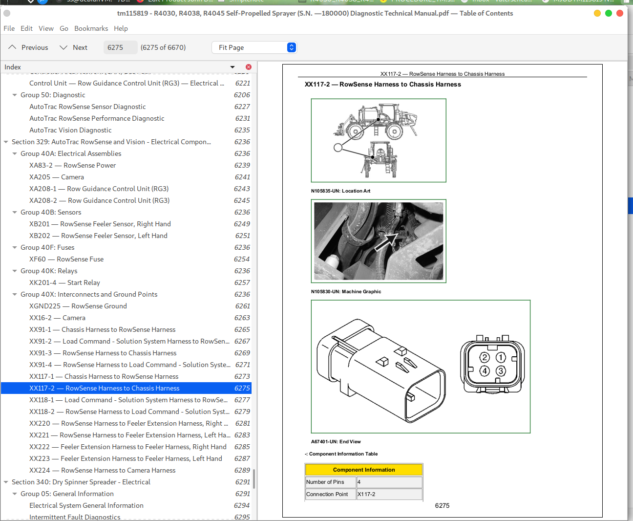
John Deere R4030 R4038 R4045 Self-Propelled Sprayer Workshop Repair & Diagnostic Manual TM115819 PDF - MJODTM115819.zip
A full-service manual covering operations, diagnostics, and testing—complete with every electrical wiring diagram—for the John Deere Self-Propelled Sprayers R4030, R4038, and R4045. Inside, you'll find all the workshop guidance needed to service, troubleshoot, fix, and rebuild these machines the way a professional technician would.
The Diagnosis & Tests technical manual for the John Deere Self-Propelled Sprayers R4030, R4038, and R4045 contains:
* Numbered table of contents easy to use so that you can find the information you need fast.
* Detailed sub-steps expand on repair procedure information
* Numbered instructions guide you through every repair procedure step by step.
* Troubleshooting and electrical service procedures are combined with detailed wiring diagrams for ease of use.
* Notes, cautions and warnings throughout each chapter pinpoint critical information.
* Bold figure number help you quickly match illustrations with instructions.
* Detailed illustrations, drawings and photos guide you through every procedure.
* Enlarged inset helps you identify and examine parts in detail.
TM115819 - John Deere R4030, R4038, R4045 Self-Propelled Sprayer Technical Manual (Diagnosis and Tests).PDF
Total Pages: 6,630 pages
File Format: PDF (PC/Mac/Android/Kindle/iPhone/iPad; bookmarked, ToC, Searchable, Printable)
Language: English
MAIN SECTIONS
Foreword
General Information
Safety
General References
Diagnostic and Testing Procedures
Diagnostic Trouble Codes
Observable Symptom and System Diagnostics
Electrical
Electronic Control Units
Drivetrain
Steering and Brakes
Hydraulics and Pneumatics
Solution System
Heating, Ventilation, and Air Conditioning
Dry Application System - Electrical
Dry Application System - Control Unit
Dry Application System - Hydraulics
Engine
Fuel, Air Intake, Exhaust and Cooling
Fuel, Air Intake, Exhaust and Cooling Systems
Electrical
General Information
Application System
Boom
Cab
CAN Bus
Engine
GreenStar
Hydraulic Electrical
Lighting
Power Train
Starting-Charging-Power Distribution
Schematic-Application System
Schematic-Boom
Schematic-Cab
Schematic-CAN Bus
Schematic-Engine
Schematic-GreenStar
Schematic-Hydraulic Electrical
Schematic-Lighting
Schematic-Power Train
Schematic-Starting, Charging and Power Distribution
Diagnostics-Application System
Diagnostics-Boom
Diagnostics-Cab
Diagnostics-CAN Bus
Diagnostics-GreenStar
Diagnostics-Hydraulic Electrical
Diagnostics-Lighting
Diagnostics-Power Train
Diagnostics-Starting, Charging and Power Distribution
Electronic Control Units
Schematic
Electrical Component Information
Electrical Assemblies
Sensors
Diodes
Lights
Fuses
Charging
Monitoring Devices
Relays
Motors
Resistors
Switches
Interconnects and Ground Points
Electronically Actuated Mechanical Devices
Drivetrain
Drivetrain Component Information
Steering, Brakes and Tread Adjust
Steering
Park Brake
Service Brakes
Steering and Brakes Component Information
Hydraulics and Pneumatics
Hydraulics Component Information
Solution System
Solution System Component Information
Heating, Ventilating, and Air Conditioning System
Special Tools
Service Tools and Kits
Dry Spinner Spreader - Electrical
General Information
Application System Theory of Operation
CAN Bus Theory of Operation
Lighting Theory of Operation
Application System Schematic
CAN Bus Schematic
Lighting Schematic
Application System Diagnostic
CAN Bus Diagnostic
Lighting Diagnostic
Diagnostic Tests and Adjustments
Dry Spinner Spreader - Electronic Control Units
Dry Spinner Spreader - Electrical Component Information
Dry Spinner Spreader - Hydraulic
Dry Spinner Spreader - Hydraulic Component Information
tm115819 - R4030, R4038, R4045 Self-Propelled Sprayer (S.N. —180000) Diagnostic Technical Manual
Table of Contents - Expanded View
Foreword
Section 210: General Information
Group 05: Safety
Recognize Safety Information
Understand Signal Words
Follow Safety Instructions
Avoid High-Pressure Fluids
Park Machine Safely
Wait Before Opening High-Pressure Fuel System
Clean Exhaust Filter Safely
Exhaust Filter Cleaning
Service Accumulator Systems Safely
Handle Fluids Safely—Avoid Fires
Prevent Battery Explosions
Prepare for Emergencies
Protect Against High Pressure Spray
Prevent Acid Burns
Wear Protective Clothing
Protect Against Noise
Handle Agricultural Chemicals Safely
Service and Operate Chemical Sprayers Safely
Avoid Contact with Agricultural Chemicals
Clean Vehicle of Hazardous Pesticides
Support Machine Properly
Service Machines Safely
Practice Safe Maintenance
Avoid Harmful Asbestos Dust
Work In Ventilated Area
Work in Clean Area
Precautions for Welding
Remove Paint Before Welding or Heating
Avoid Heating Near Pressurized Fluid Lines
Service Tires Safely
Service Cooling System Safely
Illuminate Work Area Safely
Replace Safety Signs
Use Proper Lifting Equipment
Use Proper Tools
Construct Dealer-Made Tools Safely
Decommissioning — Proper Recycling and Disposal of Fluids and Components
Live With Safety
Group 10: General References
Machine Specifications
Dimensions—All Machines
Standard Machine Dimensions
Identification Numbers
Sealants and Adhesives Cross-Reference Chart
Face Seal Fittings Assembly and Installation—All Pressure Applications
Metric Face Seal and O-Ring Stud End Fitting Torque Chart—Standard Pressures
Metric Face Seal and O-Ring Stud End Fitting Torque Chart—High Pressure Applications
SAE Face Seal and O-Ring Stud End Fitting Torque Chart—Standard Pressures
SAE Face Seal and O-Ring Stud End Fitting Torque Chart—High Pressure Applications
Four Bolt Flange Fittings Assembly and Installation—All Pressure Applications
SAE Four Bolt Flange Cap Screw Torque Values—Standard Pressure Applications
SAE Four Bolt Flange Cap Screw Torque Values—High Pressure Applications
External Hexagon Port Plug Torque Chart
Unified Inch Bolt and Screw Torque Values
Metric Bolt and Screw Torque Values
Servicing and Connecting Snap to Connect STC Fittings
Group 50: Diagnostic Philosophy
Basic Diagnostic Philosophy
Systematic Diagnostic Approach Overview
Section 211: Diagnostic Trouble Codes
Group 1: Dry Spinner Spreader - DRC — Diagnostic Trouble Codes
DRC 000158.00 - Dry Rate Controller Supply Voltage High
DRC 000158.10 - Dry Rate Controller Supply Voltage Low
DRC 000630.20 - Dry Rate Controller Calibration Fault
DRC 002071.09 - Communication Fault
DRC 003509.00 - Sensor Voltage High
DRC 003509.01 - Sensor Voltage Low
DRC 003509.04 - Sensor Voltage Open
DRC 520247.02 - Fertilizer Product Belt Not Operating Correctly
DRC 523394.02 - Spinners Not Operating Correctly
Group 2: ASM — Diagnostic Trouble Codes
ASM 000628.02 - EOL Data Checksum Error
ASM 000630.02 - EEPROM in ASM is corrupted. Default values used.
ASM 521160.08 - Key 2 of ASM is held or pressed for more that 60 seconds.
ASM 521161.08 - Key 3 of ASM is held or pressed for more than 60 seconds.
ASM 521162.08 - Key 4 of ASM is held or pressed for more that 60 seconds.
ASM 521163.08 - Key 5 of ASM is held or pressed for more that 60 seconds.
ASM 521164.08 - Key 8 of ASM is held or pressed for more than 60 seconds.
ASM 521165.08 - Key 9 of ASM is held or pressed for more than 60 seconds.
ASM 521166.08 - Key 10 of ASM is held or pressed for more than 60 seconds.
ASM 521167.08 - Key 1 of ASM is held or pressed for more than 60 seconds.
ASM 521168.08 - Key 7 of ASM is held or pressed for more than 60 seconds.
ASM 521169.08 - Key 11 of ASM is held or pressed for more than 60 seconds.
ASM 521170.08 - Key 6 of ASM is held or pressed for more than 60 seconds.
ASM 521505.08 - Key 12 of ASM is held or pressed for more that 60 seconds.
ASM 521506.08 - Key 13 of ASM is held or pressed for more than 60 seconds.
ASM 521507.08 - Key 14 of ASM is held or pressed for more than 60 seconds.
ASM 521508.08 - Key 16 of ASM is held or pressed for more than 60 seconds.
ASM 521509.08 - Key 15 of ASM is held or pressed for more than 60 seconds.
ASM 521510.08 - Key 17 of ASM is held or pressed for more than 60 seconds.
ASM 521511.08 - Key 18 of ASM is held or pressed for more than 60 seconds.
ASM 521512.08 - Key 19 of ASM is held or pressed for more than 60 seconds.
ASM 521513.08 - Key 20 of ASM is held or pressed for more than 60 seconds.
ASM 521514.08 - Key 21 of ASM is held or pressed for more than 60 seconds.
ASM 522771.31 - ASM hardware is not connected OR problem with ASM connectors.
Group 4: ATC — Diagnostic Trouble Codes
ATC 000158.03 - HVAC Control Switched Supply Voltage High.
ATC 000158.04 - HVAC Control Switched Supply Voltage Low.
ATC 000170.03 - Cab Temperature Sensor Circuit Voltage High.
ATC 000170.04 - Cab Temperature Sensor Circuit Voltage Low.
ATC 000628.12 - ATC Programming.
ATC 000639.14 - ATC CAN Error Limit Exceeded.
ATC 000871.03 - Refrigerant Pressure Sensor Circuit Voltage High.
ATC 000871.04 - Refrigerant Pressure Sensor Circuit Voltage Low.
ATC 000871.13 - Refill A/C Refrigerant.
ATC 000871.18 - Refill A/C Refrigerant.
ATC 000876.03 - Compressor Clutch, (Switched) Voltage Too High at A/C Clutch.
ATC 000876.04 - Compressor Clutch (Switched) Voltage Too Low at A/C Clutch.
ATC 000923.03 - Circulation Blower Motor Circuit Voltage High.
ATC 000923.04 - Circulation Blower Motor Circuit Voltage Low.
ATC 000923.12 - Circulation Blower Motor Driver Circuit Fault.
ATC 001546.03 - Water Valve Position Sensor Circuit Voltage High.
ATC 001546.04 - Water Valve Position Sensor Circuit Voltage Low.
ATC 001547.03 - Evaporator Temperature Sensor Circuit High Voltage.
ATC 001547.04 - Evaporator Temperature Sensor Circuit Voltage Low.
ATC 001548.03 - Outlet Air Temperature Sensor Circuit High Voltage.
ATC 001548.04 - Outlet Air Temperature Sensor Circuit Voltage Low.
ATC 001549.03 - Water Valve Motor Circuit Voltage High.
ATC 001549.04 - Water Valve Motor Circuit Voltage Low.
ATC 001549.07 - Heater Valve Fault.
ATC 001549.13 - Water Valve Motor Not Calibrated.
ATC 001551.03 - Pressurizer Blower Control Relay Driver Circuit High.
ATC 001551.04 - Pressurizer Blower Control Relay Driver Circuit Low.
ATC 002000.09 - ECU Message Missing.
ATC 002071.09 - CCU Message Missing.
ATC 002139.09 - CSM Message Missing.
ATC 003509.03 - ATC Sensor Supply Voltage High.
ATC 003509.04 - ATC Sensor Supply Low.
ATC 003509.06 - ATC Sensor Supply Voltage Low.
ATC 520870.02 - ATC Calibration Fault/Data Invalid.
ATC 520871.02 - ATC Calibration Fault/Data Invalid.
ATC 520872.02 - ATC Calibration Fault/Data Invalid.
ATC 523848.03 - Air Flow Mode Motor Circuit Voltage High.
ATC 523848.04 - Air Flow Mode Motor Circuit Voltage Low.
ATC 523848.05 - Air Flow Mode Motor Circuit Current Low.
ATC 523848.06 - Air Flow Mode Motor Circuit Current High.
ATC 523848.07 - Adjusting Motor for Air Distribution Fault.
ATC 523848.13 - Air Flow Mode Motor Not Calibrated.
ATC 524202.03 - Ambient Temperature Sensor Circuit Voltage High
ATC 524202.04 - Ambient Temperature Sensor Circuit Voltage Low.
ATC 524203.03 - Ambient Temperature Sensor Circuit Voltage High
ATC 524203.04 - Ambient Temperature Sensor Circuit Voltage Low.
ATC 524219.02 - Defog Sensor Frequency Out of Valid Range
ATC 524219.03 - Defog Sensor Voltage Too High
ATC 524219.04 - Defog Sensor Voltage Too Low
ATC 600006.31 - Default DTC.
Group 5A: BH1 — Diagnostic Trouble Codes
BH1 000158.00 - Switched system voltage high.
BH1 000158.01 - Switched system voltage low.
BH1 000628.02 - Vehicle load center control unit fault.
BH1 000629.12 - Watchdog timed out.
BH1 000630.13 - Vehicle load center control unit fault.
BH1 002071.09 - Controller Area Network (CAN) Messages from Chassis Control Unit (CCU) missing.
BH1 002246.09 - CAN Messages from multifunction lever missing
BH1 516257.03 - Center frame roll lock valve coil voltage reading from coil is above range.
BH1 516257.05 - Center Frame Roll Lock Valve Coil Current Below Normal or Open Circuit
BH1 516257.06 - Center Frame Roll Lock Valve Coil Current Above Normal or Grounded Circuit
BH1 516258.03 - Left inner boom proportional fold coil voltage reading is above range.
BH1 516258.05 - Left-Hand Inner Fold Proportional Solenoid Current Below Normal or Open Circuit
BH1 516258.06 - Left Inner Boom Proportional Fold Coil Current Above Normal or Short Circuit
BH1 516271.03 - Left-Hand Inner Boom Fold Sensor Voltage Above Normal or Shorted to High Source
BH1 516271.04 - Left-Hand Inner Boom Fold Sensor Voltage Below Normal or Shorted to Low Source
BH1 516272.03 - Left-Hand Outer Boom Fold Sensor Voltage Above Normal or Shorted to High Source
BH1 516272.04 - Left-Hand Outer Boom Fold Sensor Voltage Below Normal or Shorted to Low Source
BH1 516273.05 - Left-Hand Outer Fold Proportional Solenoid Current Below Normal or Open Circuit
BH1 516273.06 - Left-Hand Outer Boom Proportional Fold Coil Current Above Normal or Short Circuit
BH1 516275.03 - Right-Hand Inner Boom Fold Sensor Voltage Above Normal or Shorted to High Source
BH1 516275.04 - Right-Hand Inner Boom Fold Sensor Voltage Below Normal or Shorted to Low Source
BH1 516275.13 - Sensor not calibrated, sensor reading outside of calibration range.
BH1 516276.03 - Right-Hand Outer Boom Fold Sensor Voltage Above Normal or Shorted to High Source
BH1 516276.04 - Right-Hand Outer Boom Fold Sensor Voltage Below Normal or Shorted to Low Source
BH1 516276.13 - Sensor not calibrated, sensor reading outside of calibration range.
BH1 516277.05 - Right-Hand Inner Fold Proportional Solenoid Current Below Normal or Open Circuit
BH1 516277.06 - Right-Hand Inner Boom Proportional Fold Coil Current Above Normal or Short Circuit
BH1 516278.05 - Right-Hand Outer Fold Proportional Solenoid Current Below Normal or Open Circuit
BH1 516278.06 - Right Outer Boom Proportional Fold Valve Coil Current Above Normal or Short Circuit. System Functionality Limited.
BH1 516812.05 - Tilt load sense bypass coil current below normal or open circuit.
BH1 516812.06 - Tilt load sense bypass coil current above normal or short circuit.
BH1 520870.02 - Data Erratic, Intermittent or Incorrect.
BH1 520871.02 - Data Erratic, Intermittent or Incorrect.
BH1 520872.02 - Data Erratic, Intermittent or Incorrect.
BH1 522378.13 - Sensor not calibrated or outside of calibration values. System functionality may be limited.
BH1 522380.13 - Sensor not calibrated or outside of calibration values. System functionality may be limited.