
Komatsu PC27MR-2 PC27MR-3 PC30MR-2 PC30MR-3 PC35MR-2 PC35MR-3 PC40MR-2 PC50MR-2 Excavator Workshop Repair Service Manual PDF - MKMTSPC27MR35MR.zip
A full factory-level service and repair guide, complete with electrical wiring diagrams, covering the Komatsu Hydraulic Excavator models PC27MR-2, PC27MR-3, PC30MR-2, PC30MR-3, PC35MR-2, PC35MR-3, PC40MR-2, and PC50MR-2 — packed with every technical detail needed to service, troubleshoot, fix, and overhaul these machines the way expert technicians do.
Contained within this Komatsu Hydraulic Excavator PC27MR-2, PC27MR-3, PC30MR-2, PC30MR-3, PC35MR-2, PC35MR-3, PC40MR-2, PC50MR-2 workshop service and repair manual, you'll find:
* Numbered table of contents easy to use so that you can find the information you need fast.
* Detailed sub-steps expand on repair procedure information
* Numbered instructions guide you through every repair procedure step by step.
* Troubleshooting and electrical service procedures are combined with detailed wiring diagrams for ease of use.
* Notes, cautions and warnings throughout each chapter pinpoint critical information.
* Bold figure number help you quickly match illustrations with instructions.
* Detailed illustrations, drawings and photos guide you through every procedure.
* Enlarged inset helps you identify and examine parts in detail.
PRODUCT DETAILS:
Total Pages: 4,048 pages
File Format: PDF (Internal Links, Bookmarked, Table of Contents, Searchable, Printable, high quality)
Language: English
SEBM032411 - Hydraulic Excavator PC27MR-2, PC30MR-2, PC35MR-2, PC40MR-2, PC50MR-2 Shop Manual.pdf
SEN04063-07 - Hydraulic Excavator PC27MR-3, PC30MR-3, PC35MR-3 Shop Manual.pdf
TEN00099-01 - Hydraulic Excavator PC27MR-2, PC35MR-2 Operation & Maintenance Manual.pdf
TEN00115-00 - Hydraulic Excavator GALEO PC27ME-2, PC35MR-2 Operation & Maintenance Manual.pdf
TEN00115-01 - Hydraulic Excavator GALEO PC27MR-2, PC35MR-2 Operation & Maintenance Manual.pdf
TEN00194-00 - Hydraulic Excavator GALEO PC27MR-2, PC35MR-2 Operation & Maintenance Manual.pdf
TEN00284-03 - Hydraulic Excavator GALEO PC27MR-3, PC35MR-3 Operation & Maintenance Manual.pdf
TEN00378-03 - Hydraulic Excavator PC27MR-3, PC35MR-3 Operation & Maintenance Manual.pdf
TEN00507-01 - Hydraulic Excavator PC27MR-3, PC35MR-3 Operation & Maintenance Manual.pdf
TEN00552-01 - Hydraulic Excavator PC27MR-3, PC35MR-3 Operation & Maintenance Manual.pdf
WEAM006600 - Hydraulic Excavator PC30MR-2, PC35MR-2 Operation & Maintenance Manual.pdf
SEAM060100T - Hydraulic Excavator GALEO PC35MR-2 Operation & Maintenance Manual.pdf
MAIN SECTIONS
COVER...1
00 Index and foreword...0
100 Index...2
Composition of shop manual...3
Table of contents...5
200 Foreword and general information...12
Safety notice...13
How to read the shop manual...18
Explanation of terms for maintenance standard...20
Handling of electric equipment and hydraulic component...22
Handling of connectors newly used for engines...31
How to read electric wire code...34
Precautions when carrying out operation...37
Method of disassembling and connecting push-pull type coupler...40
Standard tightening torque table...43
Conversion table...47
01 Specification...0
100 Specification and technical data...54
Specification dimension drawing...55
Working range drawing...56
Specifications...57
Weight table...67
Table of fuel, coolant and lubricants...71
10 Structure, function and maintenance standard...0
100 Engine and cooling system...74
PTO...75
Cooling system...77
200 Power train...80
Power train...81
Swing circle...83
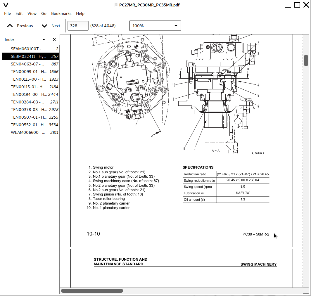
Swing machinery...84
300 Undercarriage and frame...88
Track frame...89
Idler cushion...90
Idler...91
Track roller...93
Carrier roller...94
Sprocket...95
Track shoe...96
410 Hydraulic system, Part 1...102
Hydraulic components layout drawing...103
Hydraulic tank, filter...104
Center swivel joint...106
Travel motor...108
Hydraulic cylinder...116
Solenoid valve...121
Multi-control valve...127
420 Hydraulic system, Part 2...130
Hydraulic pump...131
Control valve...147
430 Hydraulic system, Part 3...180
CLSS...181
Operation for each function and valve...185
Swing motor...225
PPC valve...230
500 Work equipment...242
Work equipment...243
Dimensions of each part of work equipment...247
600 Cab and its attachments...256
Floor...257
Air conditioner...258
700 Electrical system...260
Engine control system...261
Electric control system...265
Auto-deceleration function...275
Attachment proportional switch, breaker operation switch, work mode selection, flow control function...279
KOMTRAX system...289
Component parts of system...292
Monitor system...293
Sensors...297
20 Standard value table...0
100 Standard service value table...302
Standard service value table for engine related parts...303
Standard service value table for chassis related parts...305
30 Testing and adjusting...0
100 Testing and adjusting...330
Tools for testing, adjusting, and troubleshooting...332
Testing engine speed...335
Testing exhaust gas color...336
Testing and adjusting valve clearance...337
Testing compression pressure...338
Testing engine oil pressure...339
Testing and adjusting fuel injection timing...340
Testing and adjusting alternator belt tension...344
Testing and adjusting air conditioner compressor belt tension...345
Adjusting fuel control lever...346
Testing clearance in swing circle bearings...347
Testing and adjusting track shoe tension...348
Testing and adjusting oil pressures in work equipment, travel, boom swing, swing, and blade circuits...349
Testing and adjusting LS differential pressure...354
Adjusting PC valve...357
Testing and adjusting control pump circuit oil pressure...358
Testing solenoid valve output pressure...360
Testing PPC valve output pressure...361
Adjusting PPC valve...365
Testing swing holding brake release pressure...366
Testing and adjusting travel deviation...367
Testing oil leakage from work equipment cylinder...369
Bleeding air from each part...371
Releasing residual pressure from hydraulic circuit...373
Releasing residual pressure from hydraulic tank...374
Pressurizing hydraulic tank...374
How to open and close (tilt) floor...375
Inspection procedures for diode...380
Function and flow of operator and service mode...381
How to start operation of KOMTRAX terminal...405
Lamp display of KOMTRAX terminal...409
Removal and installation of KOMTRAX terminal...412
Preparation work for troubleshooting of electrical system...413
40 Troubleshooting...0
010 Failure code table and fuse locations...416
User code and failure code list...417
Fuse locations...418
100 General information on troubleshooting...424
Points to remember when troubleshooting...425
Sequence of events in troubleshooting...426
Checks before troubleshooting...427
Classification and procedures of troubleshooting...428
Information contained in troubleshooting table...429
Connection table for connector pin numbers...433
T- branch box and T- branch adapter table...469
110 Troubleshooting by failure code...474
Failure code [DBHRKR] Communication error between monitor panel and attachment switch controller...477
Failure code [DBH1KK] Unswitched power supply error...479
Failure code [DBH2KK] Solenoid power supply error...481
Failure code [DBH5KP] 5V sensor power supply output 0 error...483
Failure code [DBH6KP] 5V sensor power supply output 1 error...484
Failure code [DDWLKA] Breaker switch error (Disconnection or short circuit)...485
Failure code [DDWLKB] Breaker switch error (Hot short circuit)...486
Failure code [DFB1KA] Attachment switch (main) error (Disconnection or ground fault)...487
Failure code [DFB1KB] Attachment switch (main) error (Hot short circuit)...489
Failure code [DFB3L8] Attachment switch (main-sub) voltage difference error...490
Failure code [DK10KA] Fuel control dial potentiometer error (Disconnection or ground fault)...491
Failure code [DK10KB] Fuel control dial potentiometer error (Hot short circuit)...493
Failure code [DK58KA] Governor stroke sensor error (Disconnection or ground fault)...495
Failure code [DK58KB] Governor stroke sensor error (Hot short circuit)...497
Failure code [D1E0KZ] Motor power supply relay error (Disconnection or hot short circuit)...499
Failure code [D1E0KB] Motor power supply relay error (Ground fault)...501
Failure code [D1E1KZ] Motor drive relay (+) error (Disconnection or hot short circuit)...503
Failure code [D1E1KB] Motor drive relay (+) error (Ground fault)...505
Failure code [D1E2KZ] Motor drive relay (-) error (Disconnection or hot short circuit)...507
Failure code [D1E2KB] Motor drive relay (-) error (Ground fault)...509
Failure code [DY10MA] Fuel control motor operation error...511
Failure code [D1E0KA] Fuel control motor power supply relay contact sticking (NC side)...513
Failure code [D1E0KY] Fuel control motor power supply relay contact sticking (NO side)...515
Failure code [DXEAKA] EPC valve (port A side) error (Disconnection)...517
Failure code [DXEAKB] EPC valve (port B side) error (Ground fault)...519
Failure code [DXEAKY] EPC valve (port A side) error (Hot short circuit)...520
200 Troubleshooting of electrical system (E-mode)...522
Before carrying out troubleshooting of electrical system...523
E-1 Engine does not start...525
E-2 Engine does not stop...541
E-3 When starting switch is turned ON, any item does not operate...545
E-4 When starting switch is turned ON, some items do not operate...549
E-5 Alarm buzzer is abnormal...550
E-6 Engine oil pressure caution is turned ON...552
E-7 Charge level caution is turned ON...553
E-8 Preheating system does not operate or preheater does not become hot1...555
E-9 Coolant temperature gauge is abnormal...557
E-10 Fuel level gauge is abnormal...565
E-11 Service meter does not operate while engine is running...573
E-12 2nd travel speed is not selected...577
E-13 Working lamp does not light up...581
E-14 When work equipment lock (PPC basic pressure lock) lever is set in LOCK, work equipment still moves...585
E-15 Windshield wiper does not operate...589
E-16 Windshield washer does not operate...593
E-17 Defective air conditioner...596
E-18 KOMTRAX system does not operate normally...604
300 Troubleshooting of hydraulic and mechanical system (H-mode)...608
Information contained in troubleshooting table...610
H1 Speed or power of whole work equipment, travel, swing, and blade is low...611
H-2 Engine speed lowers extremely or engine stalls...615
H-3 Whole work equipment, travel system, swing system, and blade do not work...616
H-4 Abnormal sound comes out from around hydraulic pump...620
H-5 Fine control performance or response is low...620
H-6 Speed or power of boom is low...621
H-7 Speed or power of arm is low...622
H-8 Speed or power of bucket is low...623
H-9 Speed or power of boom swing is low...624
H-10 Work equipment does not move singly...624
H-11 Work equipment hydraulic drift is large...625
H-12 Time lag of work equipment is large...627
H-13 In compound operation of work equipment, speed of part loaded more is low...627
H-14 Machine deviates during travel...628
H-15 Travel speed or travel power is low (while work equipment is normal)...630
H-16 Machine is not steered well or steering power is low...631
H-17 Travel speed does not change...632
H-18 Travel motor does not work...633
H-19 Speed or power of swing is low...635
H-20 Machine does not swing...637
H-21 Swing acceleration performance is low...639
H-22 Machine overruns when it stops swinging...641
H-23 Large shock is made when machine stops swinging...642
H-24 When upper structure stops swinging, it makes large sound...642
H-25 Hydraulic drift of swing is large...643
H-26 Speed or power of blade is low...644
H-27 Blade does not move...645
H-28 Hydraulic drift of blade is large...646
400 Troubleshooting of engine (S-mode)...648
Method of using troubleshooting charts...650
S-1 Starting performance is poor...653
S-2 Engine does not start...654
S-3 Engine does not pick up smoothly...657
S-4 Engine stops during operations...658
S-5 Engine does not rotate smoothly...659
S-6 Engine lacks output (or lacks power)...660
S-7 Exhaust smoke is black (incomplete combustion)...661
S-8 Oil consumption is excessive (or exhaust smoke is blue)...662
S-9 Oil becomes contaminated quickly...663
S-10 Fuel consumption is excessive...664
S-11 Oil is in coolant (or coolant spurts back or coolant level goes down)...665
S-12 Oil pressure drops...666
S-13 Oil level rises (Entry of coolant/fuel)...667
S-14 Coolant temperature becomes too high (overheating)...668
S-15 Abnormal noise is made...669
S-16 Vibration is excessive...670
50 Disassembly and assembly...0
100 General information on disassembly and assembly...672
How to read this manual...673
Coating materials list...675
Special tool list...678
Sketches of special tools...682
200 Engine and cooling system...684
Removal and installation of fuel injection pump assembly...685
Removal and installation of radiator and hydraulic oil cooler assembly...688
Removal and installation of engine and hydraulic pump assembly...692
300 Power train...696
Removal and installation of swing motor and swing machinery assembly...697
Disassembly and assembly of swing motor and swing machinery assembly...698
Removal and installation of swing circle assembly...703
400 Undercarriage and frame...706
Removal and installation of track shoe assembly...707
Disassembly and assembly of idler assembly...708
Disassembly and assembly of recoil spring assembly...710
Disassembly and assembly of track roller assembly...713
Disassembly and assembly of carrier roller assembly...714
Removal and installation of revolving frame assembly...715
500 Hydraulic system...718
Removal and installation of center swivel joint assembly...719
Disassembly and assembly of center swivel joint assembly...721
Disassembly and assembly of control valve assembly...723
Disassembly and assembly of hydraulic cylinder assembly...724
600 Work equipment...730
Removal and installation of work equipment assembly...731
700 Cab and its attachments...734
Removal and installation of operator?s cab glass (stuck glass)...735
Removal and installation of front window assembly...744
Removal and installation of floor frame assembly...745
800 Electrical system...750
Removal and installation of air conditioner unit assembly (If equipped)...751
90 Diagrams and drawings...0
100 Hydraulic diagrams and drawings...756
Hydraulic circuit diagram...758
200 Electrical diagrams and drawings...766
Electrical circuit diagram...768
Connector list and stereogram...776
COVER...1
FOREWORD...2
FOREWORD...3
SAFETY INFORMATION...6
INTRODUCTION...8
DIRECTIONS OF MACHINE...8
PRODUCT INFORMATION...9
PRODUCT IDENTIFICATION NUMBER (PIN)/MACHINE SERIAL NO. PLATE...9
ENGINE SERIAL NUMBER PLATE AND ITS LOCATION...9
EMISSION CONTROL INFORMATION LABEL AND ITS LOCATION...10
SERVICE METER LOCATION...10
YOUR MACHINE SERIAL NUMBERS AND DISTRIBUTOR...11
CONTENTS...12
SAFETY...15
SAFETY INFORMATION...16
SAFETY LABELS...18
LOCATION OF SAFETY LABELS...18