
Mitsubishi Lancer Evolution EVO1-10 Workshop Repair Manual 1992-2016 PDF - MMTBSLE9216OPES.zip
Full service and repair documentation, complete with Electrical Wiring Diagrams, covering the Mitsubishi Lancer Evolution from 1992 through 2016 — everything you need to service, troubleshoot, fix, and rebuild these cars the way a professional technician would.
The Mitsubishi Lancer Evolution 1992-2016 workshop service repair manual contains:
* Numbered table of contents easy to use so that you can find the information you need fast.
* Detailed sub-steps expand on repair procedure information
* Numbered instructions guide you through every repair procedure step by step.
* Troubleshooting and electrical service procedures are combined with detailed wiring diagrams for ease of use.
* Notes, cautions and warnings throughout each chapter pinpoint critical information.
* Bold figure number help you quickly match illustrations with instructions.
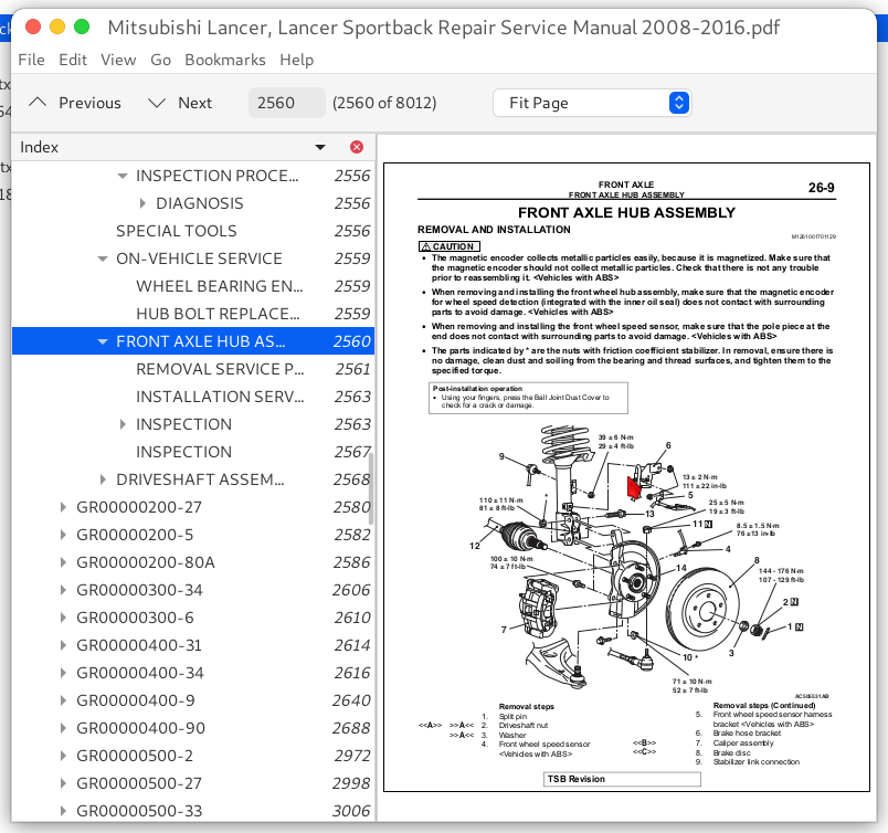
* Detailed illustrations, drawings and photos guide you through every procedure.
* Enlarged inset helps you identify and examine parts in detail.
'01-'05 EVO7-8.pdf
'03-'08 EVO8-10.pdf
'03 EVO8.pdf
'04 EVO8.pdf
'05-'08 EVO9.pdf
'08 EVO10.pdf
'10 EVO10.pdf
'92-'96 EVO1-2-3.pdf
'97-'99 EVO4-5.pdf
12LancerEvo '12 (MUT-III).iso
CCZG13E1 '13 (MUT-III).iso
EVO8 MR Supplement.pdf
PRODUCT DETAILS:
Total Pages: 2.2 GB / 31,332 pages
File Format: PDF / DVD iso disc image
Language: English
TABLE OF CONTENTS
10_GS41EVO_MMNA_SM....1
08_GS41EVO_MMNA_BRM_PDF....1
GR00000800-1....1
BODY CONSTRUCTION....1
BODY COMPONENTS....2
BODY MAIN CROSS-SECTIONAL VIEWS....4
MAINTENANCE, SERVICEABILITY....6
FENDER SHIELD....6
SIDE STRUCTURE....7
SIDE OUTER PANEL....7
BODY CONSTRUCTION CHARACTERISTICS....8
HEADLIGHT SUPPORT....8
FENDER SHIELD....9
FRONT SIDEMEMBER REINFORCEMENT....11
FRONT DECK....13
DASH PANEL....14
SIDE STRUCTURE....15
SIDE STRUCTURE REINFORCEMENT....17
FRONT FLOOR....20
REAR FLOOR....21
REAR FLOOR SIDEMEMBER REINFORCEMENT....22
SILENCER APPLICATION LOCATIONS....25
FOAMING MATERIAL USAGE LOCATIONS....26
STIFFENER AND DAMP SHEET APPLICATION LOCATIONS....27
THEFT PROTECTION....28
GR00000900-2....33
BODY DIMENSIONS....33
BODY DIMENSIONS AND MEASUREMENT METHODS....34
TYPE A (PROJECTED DIMENSIONS)....36
TYPE B (ACTUAL-MEASUREMENT DIMENSIONS)....42
GR00001000-9....59
BASE OF BODY REPAIR....59
GENERAL....60
WELDING....60
FUSION WELDING....60
PRESSURE WELDING....60
BRAZING....60
ADVANTAGES OF ELECTRIC RESISTANCE SPOT WELDING....61
PLUG WELDING....68
CONTINUOUS WELDING....69
NOTES REGARDING MIG WELDING....70
BRAZING....70
Notes with regard to brazing work....70
GAS WELDING....71
BODY REPAIR....72
STANDARD PROCEDURES FOR REPLACEMENT OF WELDED PANELS....72
CAUTIONS REGARDING BODY REPAIR....80
THEFT PROTECTION....81
PANEL REPAIR CAUTION....81
HOW TO PEEL OFF THE SURFACE MASKING FILM FROM THE THEFT-PROTECTION LABEL....81
REPAIRS USING A HAMMER AND DOLLY....84
OVERALL ROUGH REPAIRS....85
FRAME STRAIGHTENING NOTES....86
CHECKING FOR FRAME CRACKING OR FLAKING....86
REPAIRING CRACKS....86
NOTES REGARDING REPAIR WORK....89
SAFETY MEASURES....89
HEALTH AND SANITATION PROCEDURES....91
VEHICLE PROTECTION....91
CORROSION PROTECTION....95
ZINC PHOSPHATE COATING....95
BODY SEALING....96
UNDERBODY COATING....96
WAX INJECTION....97
SEALING TAPE....97
ANTICORROSION TREATMENT AT THE TIME OF BODY REPAIR WORK....98
CORROSION PROTECTION FOR HOLLOW PARTS....98
ANTICORROSION TREATMENT OF ROUGH CUTS....98
SPOT SEALER....98
BODY SEALING....99
REPAIR OF SYNTHETIC-RESIN PARTS....101
REPAIR JUDGMENT....102
REPAIR PROCEDURE....102
GR00001100-3....107
WELDED PANEL REPLACEMENT....107
ULTRA HIGH STRENGTH STEEL PLATE....108
ADVANTAGES OF ULTRA HIGH STRENGTH STEEL PLATE....108
PRECAUTION UPON MAINTENANCE OF ULTRA HIGH STRENGTH STEEL PLATE....108
FRONT END CROSSMEMBER....109
FENDER SHIELD....110
NOTE ON REPAIR WORK....113
FRONT SIDEMEMBER (PARTIAL REPLACEMENT)....114
FRONT PILLAR....115
NOTE ON REPAIR WORK....117
FRONT PILLAR (PARTIAL REPLACEMENT)....121
NOTE ON REPAIR WORK....122
CENTER PILLAR....125
NOTE ON REPAIR WORK....126
SIDE SILL....129
NOTE ON REPAIR WORK....131
QUARTER OUTER....135
NOTE ON REPAIR WORK....137
REAR END PANEL....139
ROOF....140
NOTE ON REPAIR WORK ....141
REAR FLOOR....143
NOTE ON REPAIR WORK....144
QUARTER INNER....145
NOTE ON REPAIR WORK....148
QUARTER INNER (PARTIAL REPLACEMENT)....150
NOTE ON REPAIR WORK....151
FRONT DOOR OUTER PANEL (WELDED TYPE)....152
FRONT DOOR OUTER PANEL (ADHESION TYPE)....153
NOTE ON REPAIR WORK....153
REAR DOOR OUTER PANEL (WELDED TYPE)....154
REAR DOOR OUTER PANEL (ADHESION TYPE)....155
NOTE ON REPAIR WORK....155
ALUMINUM PANEL....156
Description of aluminum panel....156
Advantage of aluminum panel....156
Correction of uneven surface....158
Operation procedure of MIG welding....159
Other welding....161
Finish with putty....162
GR00001200-4....165
CORROSION PROTECTION....165
BODY SEALING LOCATIONS....166
FLOOR....166
UPPER BODY....166
SIDE BODY....167
UNDERCOAT APPLICATION LOCATIONS....174
GR00001300-5....175
SYNTHETIC-RESIN PARTS....175
LOCATION OF SYNTHETIC-RESIN PARTS....176
GR00001400-6....179
BODY COLOR....179
BODY COLOR CODE....180
BODY COLOR CHARTS....180
BODY COLORING....181
Manual description_BRM....185
PrefaceForBRM_MMNA....186
GR00000100-52....187
INTERIOR AND SUPPLEMENTAL RESTRAINT SYSTEM(SRS)....187
GR00000200-80A....189
CONFIGURATION DIAGRAMS....189
OVERALL CONFIGURATION DIAGRAM....190
HOW TO READ CONFIGURATION DIAGRAMS....191
ENGINE COMPARTMENT....192
ENGINE AND TRANSAXLE....194
DASH PANEL....198
FLOOR AND ROOF....204
DOOR....206
LUGGAGE COMPARTMENT....208
GR00000300-52B....209
SUPPLEMENTAL RESTRAINT SYSTEM (SRS)....209
GENERAL INFORMATION....211
SRS AIR BAG SPECIAL CONNECTOR....218
SERVICE PRECAUTIONS....232
SRS AIR BAG DIAGNOSIS....234
DIAGNOSTIC FUNCTION....235
HOW TO CONNECT THE SCAN TOOL (M.U.T.-III)....235
HOW TO READ AND ERASE DIAGNOSTIC TROUBLE CODES....236
SRS WARNING LIGHT CHECK....236
PASSENGER'S SEAT BELT WARNING LIGHT CHECK....237
PASSENGER'S AIR BAG OFF INDICATOR LIGHT CHECK....237
DIAGNOSTIC TROUBLE CODE PROCEDURES ....242
DTC B1206: Passenger’s Air Bag OFF Indicator Light (Open Circuit)....242
DIAGNOSIS....243
STEP 1. Using scan tool MB991958, diagnose the CAN bus line.....243
STEP 2. Recheck for diagnostic trouble code.....244
STEP 3. Check the passenger’s air bag OFF indicator light.....244
STEP 4. Check the harness for open circuit between SRS-ECU connector C-37 (terminal No.18) and the instrument center panel connector C-124 (terminal No.11).....244
STEP 5. Measure the voltage at the instrument center panel connector.....245
STEP 6. Recheck for diagnostic trouble code.....245
DTC B1207: Passenger’s Air Bag OFF Indicator Light (Short Circuit between Circuit Terminal)....246
DIAGNOSIS....247
STEP 1. Using scan tool MB991958, diagnose the CAN bus line.....247
STEP 2. Recheck for diagnostic trouble code.....248
STEP 3. Check the passenger’s air bag OFF indicator light.....248
STEP 4. Resistance measurement at the C-37 SRS-ECU connector.....248
STEP 5. Resistance measurement at the C-37 SRS-ECU connector.....249
STEP 6. Recheck for diagnostic trouble code.....249
DTC B1B00: Driver's Air Bag Module (1st Squib) System (Shorted to Squib Circuit Ground) DTC B1B04: Driver's Air Bag Module (2nd Squib) System (Shorted to Squib Circuit Ground)....250
DIAGNOSIS....251
STEP 1. Using scan tool MB991958, diagnose the CAN bus line.....251
STEP 2. Recheck for diagnostic trouble code.....252
STEP 3. Check the driver's air bag module.....253
STEP 4. Check the clock spring.....254
STEP 5. Check the driver’s air bag module circuit. Measure the resistance at the SRS-ECU connector C-37.....255
STEP 6. Check the harness for short circuit to ground between the following connector.....256
STEP 7. Recheck for diagnostic trouble code.....256
DTC B1B01: Driver's Air bag Module (1st squib) System (Shorted to Squib Circuit Power Supply) DTC B1B05: Driver's Air bag Module (2nd squib) System (Shorted to Squib Circuit Power Supply....257
DIAGNOSIS....258
STEP 1. Using scan tool MB991958, diagnose the CAN bus line.....258
STEP 2. Recheck for diagnostic trouble code.....259
STEP 3. Check the driver's air bag module.....260
STEP 4. Check the clock spring.....261
STEP 5. Check the driver’s air bag module circuit. Measure the voltage at the SRS-ECU connector C-37.....262
STEP 6. Check the harness for short circuit to power supply between the following connector.....263
STEP 7. Recheck for diagnostic trouble code.....263
DTC B1B02: Driver's Air Bag Module (1st squib) System (Squib Circuit Open) DTC B1B06: Driver's Air Bag Module (2nd squib) System (Squib Circuit Open)....264
DIAGNOSIS....265
STEP 1. Using scan tool MB991958, diagnose the CAN bus line.....266
STEP 2. Recheck for diagnostic trouble code.....266
STEP 3. Check the driver's air bag module.....267
STEP 4. Check the clock spring.....268
STEP 5. Check the harness for open circuit between the SRS-ECU connector C-37 and the clock spring connector C-208.....269
STEP 6. Recheck for diagnostic trouble code.....270
DTC B1B03: Driver's Air Bag Module (1st squib) System (Short Circuit Between Squib Circuit Terminals) DTC B1B07: Driver's Air Bag Module (2nd squib) System (Short Circuit Between Squib Circuit Terminals)....271
DIAGNOSIS....272
STEP 1. Using scan tool MB991958, diagnose the CAN bus line.....273
STEP 2. Recheck for diagnostic trouble code.....273
STEP 3. Check SRS-ECU connector C-37, driver’s air bag module connector C-204 and clock spring connector C-208.....274
STEP 4. Check the driver's air bag module.....275
STEP 5. Check the clock spring.....276
STEP 6. Check the driver’s air bag module circuit. Measure the resistance at SRS-ECU connector C-37.....277
STEP 7. Check the harness for short circuit between the harness wire and wire.....278
STEP 8. Recheck for diagnostic trouble code.....278
DTC B1B08: Passenger's (Front) Air Bag Module (1st squib) System (Shorted to Squib Circuit Ground) DTC B1B0C: Passenger's (Front) Air Bag Module (2nd squib) System (Shorted to Squib Circuit Ground)....279
DIAGNOSIS....280
STEP 1. Using scan tool MB991958, diagnose the CAN bus line.....280
STEP 2. Recheck for diagnostic trouble code.....281
STEP 3. Check the passenger's (front) air bag module.....281
STEP 4. Check the passenger's (front) air bag module circuit. Measure the resistance at the SRS-ECU connector C-37.....282
STEP 5. Check the harness wires for short circuit to ground between the following connector.....283
STEP 6. Recheck for diagnostic trouble code.....283
DTC B1B09: Passenger's (Front) Air Bag Module (1st squib) System (Shorted to Squib Circuit Power Supply) DTC B1B0D: Passenger's (Front) Air Bag Module (2nd squib) System (Shorted to Squib Circuit Power Supply....284
DIAGNOSIS....285
STEP 1. Using scan tool MB991958, diagnose the CAN bus line.....285
STEP 2. Recheck for diagnostic trouble code.....286
STEP 3. Check the passenger's (front) air bag module.....286
STEP 4. Check the passenger’s (front) air bag module circuit. Measure the voltage at the SRS-ECU connector C-37.....287
STEP 5. Check the harness wires for short circuit to power supply between the following connector.....288
STEP 6. Recheck for diagnostic trouble code.....288
DTC B1B0A: Passenger's (Front) Air Bag Module (1st squib) System (Squib Circuit Open) DTC B1B0E: Passenger's (Front) Air Bag Module (2nd squib) System (Squib Circuit Open)....289
DIAGNOSIS....290
STEP 1. Using scan tool MB991958, diagnose the CAN bus line.....290
STEP 2. Recheck for diagnostic trouble code.....291
STEP 3. Check the passenger's (front) air bag module.....291
STEP 4. Check the harness for open circuit between SRS-ECU connector C-37 and the passenger's (front) air bag module connector C-14.....292
STEP 5. Recheck for diagnostic trouble code.....293
DTC B1B0B: Passenger's (Front) Air Bag Module (1st squib) System (Short Circuit Between Squib Circuit Terminals) DTC B1B0F: Passenger's (Front) Air Bag Module (2nd squib) System (Short Circuit Between Squib Circuit Terminals)....294
DIAGNOSIS....295
STEP 1. Using scan tool MB991958, diagnose the CAN bus line.....295
STEP 2. Recheck for diagnostic trouble code.....296
STEP 3. Check SRS-ECU connector C-37 and passenger’s (front) air bag module connector C-14.....296
STEP 4. Check the passenger's (front) air bag module.....297
STEP 5. Check the passenger’s (front) air bag module circuit at SRS-ECU connector C-37.....298
STEP 6. Check the harness for short circuit between the harness wire and wire.....299
STEP 7. Check for diagnostic trouble code.....299
DTC B1B10: Driver's Knee Air Bag (Squib) System (Shorted To Squib Circuit Ground)....300
DIAGNOSIS....301
STEP 1. Using scan tool MB991958, diagnose the CAN bus line.....301
STEP 2. Recheck for diagnostic trouble code.....301
STEP 3. Check the Knee air bag module.....302
STEP 4. Check the knee air bag module circuit. Measure the resistance at the SRS-ECU connector C-37.....303
STEP 5. Check harness wires for short circuit to ground between SRS-ECU connector C-37 (terminal No.1 and 2) and knee air bag module connector C-39 (terminal No.2 and 1).....304
STEP 6. Recheck for diagnostic trouble code.....304
DTC B1B11: Driver's Knee Air Bag (Squib) System (Shorted To Squib Circuit Power Supply)....305
DIAGNOSIS....306
STEP 1. Using scan tool MB991958, diagnose the CAN bus line.....306
STEP 2. Recheck for diagnostic trouble code.....306
STEP 3. Check the knee air bag module.....307
STEP 4. Check the knee air bag module circuit. Measure the voltage at the SRS-ECU connector C-37.....308
STEP 5. Check the harness wires for short circuit to power supply between SRS-ECU connector C-37 (terminal No.1 and 2) and knee air bag module connector C-39 (terminal No.2 and 1).....309
STEP 6. Recheck for diagnostic trouble code.....309
DTC B1B12: Driver's Knee Air Bag (Squib) System (Squib Circuit Open)....310
DIAGNOSIS....311
STEP 1. Using scan tool MB991958, diagnose the CAN bus line.....311
STEP 2. Recheck for diagnostic trouble code.....311
STEP 3. Check the knee air bag module.....312
STEP 4. Check the harness for open circuit between SRS-ECU connector C-37 and the knee air bag module C-39.....313
STEP 5. Recheck for diagnostic trouble code.....314
DTC B1B13: Driver's Knee Air Bag (Squib) System (Short Circuit Between Squib Circuit Terminals)....315
DIAGNOSIS....316
STEP 1. Using scan tool MB991958, diagnose the CAN bus line.....316
STEP 2. Recheck for diagnostic trouble code.....317
STEP 3. Check SRS-ECU connector C-37 and Knee air bag module connector C-39.....317
STEP 4. Check the knee air bag module.....318
STEP 5. Check the knee air bag module circuit. Measure the resistance at the SRS-ECU connector C-37.....319
STEP 6. Check the harness for short circuit between SRS-ECU connector C-37 (terminal No.1 and 2) and knee air bag module connector C-39 (terminal No.2 and 1).....320
STEP 7. Recheck for diagnostic trouble code.....320
DTC B1B18: Curtain Air Bag Module (LH) (Squib) System (Shorted to Squib Circuit Ground)....321