
John Deere PowerTech 4.5L & 6.8L Diesel Engines Component Technical Manual CTM104 Repair Service PDF - MJODCTM104.zip
A full workshop manual covering the John Deere PowerTech 4.5L and 6.8L diesel engines, packed with the complete service data needed to service, troubleshoot, and rebuild these engines with the skill of a certified technician.
CTM104 (07NOV12) (ENGLISH) - John Deere PowerTech 4.5L & 6.8L Diesel Engines - John Deere Base Engine Component Technical Manual.pdf
CTM104 (19JUN00) - John Deere PowerTech 4.5L & 6.8L Diesel Engines - John Deere Base Engine Component Technical Manual.pdf
ctm105 - Moteurs diesel 4,5 et 6,8 l (Moteur standard) - (Édition internationale) Component Technical Manual.pdf
ctm106 - 4,5-l- und 6,8-l-Dieselmotoren (Grundmotor) - (Weltweite Ausgabe) Component Technical Manual.pdf
ctm107 - Motores diésel de 4.5 l y 6.8 l (Motor básico) - (Edición mundial) Component Technical Manual.pdf
ctm116 - Motori diesel da 4,5 l e 6,8 l (Motore base) - (Edizione universale) Component Technical Manual.pdf
ctm117 - 4,5 EN 6,8 L DIESELMOTOREN (STANDAARDMOTOR) - (WERELDWIJDE UITGAVE) Component Technical Manual.pdf
ctm165 - VZNĚTOVÉ MOTORY 4.5 l A 6.8 l (ZÁKLADNÍ MOTOR) (CELOSVĚTOVÉ VYDÁNÍ) Technický manuál komponentů.pdf
ctm180 - 4.5 升和 6.8 升柴油发动机 (基本发动机) - (世界通用机型) Component Technical Manual.pdf
ctm205 - Дизельные двигатели объемом 4,5 л и 6,8 л (основной двигатель) - (Исполнение для всех стран) Component Technical Manual.pdf
ctm206 - Motores Diesel 4,5 L e 6,8 L (Motor Básico) - (Edição Mundial) Component Technical Manual.pdf
ctm426 - 4,5 L OG 6,8 L DIESELMOTORER (BASISMOTOR) (GLOBAL UDGAVE) Komponent teknisk manual (Danish).pdf
ctm427 - 4,5 L:N JA 6,8 L:N DIESELMOOTTORIT (PERUSMOOTTORI) (MAAILMANLAAJUINEN PAINOS) Komponentin tekninen käsikirja (FIN).pdf
ctm428 - 4,5 L- OG 6,8 L DIESELMOTORER (GRUNNMOTOR) (GLOBAL VERSJON) Komponent teknisk håndbok (NOR).pdf
ctm429 - 4,5 L ÉS 6,8 L DÍZEL MOTOROK (ALAP MOTOR) (EGÉSZ VILÁGON ÉRVÉNYES KIADÁS) Alkatrész műszaki kézikönyv (HU).pdf
ctm430 - SILNIKI WYSOKOPRĘŻNE 4,5 L I 6,8 L (SILNIK PODSTAWOWY) (EDYCJA OGÓLNOŚWIATOWA) Podręcznik techniczny komponentów (Polish).pdf
ctm463 - ΚΙΝΗΤΗΡΕΣ ΝΤΙΖΕΛ 4,5 L ΚΑΙ 6,8 L (ΒΑΣΙΚΟΣ ΚΙΝΗΤΗΡΑΣ) (ΔΙΕΘΝΗΣ ΕΚΔΟΣΗ) Τεχνικό εγχειρίδιο εξαρτημάτων (Greek).pdf
ctm464 - 4,5 L i 6,8 L DIZELSKI MOTORI (OSNOVNI MOTOR) (SVJETSKO IZDANJE) Tehnički priručnik za komponente (Croatian).pdf
ctm465 - 4,5 L IR 6,8 L DYZELINIAI VARIKLIAI (BAZINIS VARIKLIS) (TARPTAUTINIS LEIDINYS) Komponento techninis vadovas (Lithuanian).pdf
ctm471 - DIZELSKI MOTORJI 4,5 L IN 6,8 L (OSNOVNI MOTOR) (IZVEDBA ZA VSE CELINE IN DRŽAVE) Technická príručka komponentov (Slovenian).pdf
ctm472 - NAFTOVÉ MOTORY S OBJEMOM 4,5 L A 6,8L(ZÁKLADNÝ MOTOR) (CELOSVETOVÉ VYDANIE) Bileşen Teknik Kılavuzu (Slovak).pdf
ctm473 - 4,5 l VE 6,8 l DİZEL MOTORLAR (ANA MOTOR) (DÜNYA ÇAPINDAKİ SÜRÜM) Bileşen Teknik Kılavuzu (Turkish).pdf
ctm474 - DIZEL MOTORI OD 4,5 L I 6,8 L (OSNOVNI MOTOR) (SVETSKO IZDANJE) Komponenta Tehnički priručnik (Bosnian).pdf
ctm731 - MOTOARE DIESEL DE 4,5 L ŞI 6,8 L (MOTORUL DE BAZĂ) (EDIŢIE MONDIALĂ) Manual tehnic pentru componente (RO).pdf
CTM104 (07NOV12) (ENGLISH) - John Deere PowerTech 4.5L & 6.8L Diesel Engines - John Deere Base Engine Component Technical Manual.pdf
CTM104 (19JUN00) - John Deere PowerTech 4.5L & 6.8L Diesel Engines - John Deere Base Engine Component Technical Manual.pdf
CTM104 - John Deere PowerTech 4.5L & 6.8L Diesel Engines - John Deere Base Engine Component Technical Manual.pdf
CTM528 (Hebrew) - ג'ון דיר PowerTech 4.5L ו-6.8L מנועי דיזל אלקטרוניים 11 מפלסים רכיבים מדריך טכני.pdf
CTM704 (Arabic) - John Deere PowerTech 4.5L & 6.8L محركات الديزل الإلكترونية ذات 11 مستوى من الدليل الفني للمكونات.pdf
CTM705 (Korean) - John Deere PowerTech 4.5L 및 6.8L 디젤 엔진 전자 11 레벨 구성 요소 기술 매뉴얼.pdf
PRODUCT DETAILS:
Total Pages: 1,760 pages
File Format: PDF (bookmarked, ToC, Searchable, Printable, high quality) & EPUB/MOBI/AZW for Kindle etc.
Language: English etc...
MAIN SECTIONS
Introduction....2
Forward....2
John Deere Dealers....3
POWERTECH 4.5 L Engine....5
POWERTECH 6.8 L Engine....6
Contents....7
General Information....9
Safety....11
Handle Fluids SafelyAvoid Fires....11
Handle Starting Fluid Safely....11
Service Cooling System Safely....12
Prevent Battery Explosions....12
Prepare for Emergencies....13
Handling Batteries Safely....14
Avoid High-Pressure Fluids....15
Wear Protective Clothing....15
Service Machines Safely....16
Work In Ventilated Area....16
Work in Clean Area....17
Remove Paint Before Welding or Heating....17
Avoid Heating Near Pressurized Fluid Lines....18
Illuminate Work Area Safely....18
Use Proper Lifting Equipment....19
Construct Dealer-Made Tools Safely....19
Practice Safe Maintenance....20
Use Proper Tools....20
Dispose of Waste Properly....21
Live With Safety....21
Engine Identification....23
Engine Model Designation....23
Engine Serial Number Plate Information ....24
OEM Engine Option Code Label....25
Engine Application Charts....26
Fuels, Lubricants and Coolants....33
Diesel Fuel ....33
Lubricity of Diesel Fuel....33
Engine Break-In Oil ....34
Diesel Engine Oil ....35
Extended Diesel Engine Oil Service Intervals....35
Alternative and Synthetic Lubricants ....36
Mixing of Lubricants....36
OILSCAN, OILSCAN Plus and COOLSCAN ....37
Grease....38
Diesel Engine Coolant Recommendations....39
Engine Coolant Specifications....40
Testing Diesel Engine Coolant ....43
Replenishing Supplemental Coolant Additives (SCAs) Between Coolant Changes....44
Operating in Warm Temperature Climates....45
Flush and Service Cooling System....46
Disposing of Coolant....47
Repair and Adjustments....49
Engine Rebuild....53
Engine Overhaul Guidelines....53
Engine Repair Stand....53
Engine Stand Safety Precautions ....54
Install Adapters on Engine Repair Stand....55
Engine Lifting Procedure....56
Clean Engine....57
Disconnect Turbocharger Oil Inlet Line....58
Mount Engine on Repair Stand....59
Engine Mounted on Repair Stand....60
Engine Disassembly Sequence....61
Sealant Application Guidelines....63
Engine Assembly Sequence....65
Engine Break-In Guidelines ....67
Perform Engine Break-In ....68
Cylinder Head and Valves....71
Check and Adjust Valve Clearance....71
Measure Valve Lift....74
Remove Cylinder Head....76
Disassemble and Inspect Rocker Arm Shaft Assembly....83
Assemble Rocker Arm Assembly....84
Inspect, Measure, and Install Fuel Supply Pump Push RodIf Applicable....84
Inspect, Measure, and Assemble Camshaft Followers....86
Measure Valve Recess in Cylinder Head....88
Preliminary Cylinder Head and Valve Checks ....89
Remove Valve Assembly....90
Inspect and Measure Valve Springs....90
Inspect Valve Rotators....91
Clean Valves....91
Inspect and Measure Valves....92
Grind Valves....93
Head Gasket Inspection and Repair Sequence....94
Inspect and Clean Cylinder Head....95
Check Cylinder Head Flatness....96
Measure Cylinder Head Thickness....97
Clean Injection Nozzle Bores....98
Clean Valve Guides....98
Measure Valve Guides....99
Knurl Valve Guides....100
Clean and Inspect Valve Seats....100
Grind Valve Seats....101
Remove Valve Seat Inserts....103
Measure Valve Seat Bore in Cylinder Head....106
Install Valve Seat Inserts....107
Install Valves....107
Clean and Inspect Cylinder Head Cap Screws....108
Inspect and Clean Exhaust Manifold....108
Clean and Inspect Top Deck of Cylinder Block....109
Measure Cylinder Liner Standout (Height above Block)....110
Install Cylinder Head....110
Torque-Turn Method for Proper Torque....113
Install Rocker Arm Assembly....114
Inspect and Clean Ventilator Outlet Hose....114
Install Rocker Arm Cover....115
Complete Final Assembly....116
Cylinder Block, Liners, Pistons and Rods....121
Connecting RodsGeneral Information....121
Remove Pistons and Connecting Rods ....122
Remove Cylinder Liners....125
Complete Disassembly of Cylinder Block (If Required)....127
Preliminary Liner, Piston and Rod Checks ....128
Disassemble Piston and Rod Assembly ....129
Clean Pistons....130
Visually Inspect Pistons....131
Clean Cylinder Liners....132
Visually Inspect Cylinder Liners....133
Check Piston Ring Groove Wear ....135
Measure Piston Pin Bore....136
Measure Piston Skirt....136
Measure Piston Height....136
Determine Piston-to-Liner Clearance ....137
Deglaze Cylinder Liners....139
Replace Piston and Liner Sets....139
Inspect and Measure Connecting Rod Bearings (Rods Removed from Engine)....140
Inspect and Measure Connecting Rod Bearings (Rod and Crankshaft in Engine)....141
Inspect Rod and Cap....142
Inspect Piston Pins and Bushings....144
Remove Piston Pin Bushing....145
Clean and Inspect Connecting Rod Pin Bore....147
Install Piston Pin Bushing in Connecting Rod....148
Measure Rod Center-to-Center Bores....149
Inspect and Clean Cylinder Block....150
Clean Cylinder Liner O-Ring Bore....152
Measure Cylinder Block Main Bearing Bore....153
Measure Camshaft Follower Machined Bore in Block....153
Measure Camshaft Bushing Bores in Block....154
Measure Balancer Shaft Bushing ID in Block4-Cylinder Engines....155
Measure Cylinder Liners and Block Bores ....156
Measure Liner Flange Counterbore Depth in Block....156
Measure Liner Flange Thickness....157
Measure Cylinder Block Top Deck Flatness....157
Remove, Inspect, and Install Piston Cooling Orifices....158
Measure Fuel Supply Pump Push Rod Bore and Push Rod OD....159
Measure Cylinder Liner Standout (Height above Block)....160
Install Packing on Cylinder Liner and O-Rings in Block....161
Install Cylinder Liner in Block....163
Assemble Piston and Connecting Rod ....165
Install Piston Rings....166
Install Piston and Connecting Rod Assembly ....167
Torque-Turn Connecting Rod Cap Screws....171
Check Engine Rotation for Excessive Tightness....172
Measure Piston Protrusion....173
Complete Final Assembly....174
Crankshaft, Main Bearings and Flywheel....175
Crankshaft and Main Bearing Failure Analysis ....175
Inspect Vibration Damper....176
Remove Pulley or Vibration Damper and Pulley ....177
Install Pulley or Vibration Damper and Pulley ....178
Replace Front Crankshaft Oil Seal and Wear Sleeve ....179
Check Crankshaft End Play....186
Inspect Flywheel....186
Check Flywheel Face Flatness....187
Check Pilot Bearing Bore Concentricity ....187
Remove Flywheel....188
Replace Flywheel Ring Gear....189
Replace Pilot Bearing in FlywheelIf Equipped....190
Install Flywheel....191
Crankshaft Rear Oil Seal and Wear Sleeve Handling Precautions....192
Remove Crankshaft Rear Oil Seal and Wear Sleeve ....192
Clean and Inspect Crankshaft Flange....197
Install Crankshaft Rear Oil Seal and Wear Sleeve....197
Remove Flywheel Housing....200
Remove and Install Crankshaft Timing Wheel (Engines with VP44 Fuel Injection Pump) ....201
Remove Crankshaft Main Bearings ....202
Check Main Bearing Oil Clearance ....203
Remove and Install Crankshaft Gear (Crankshaft Installed in Engine)....204
Remove Crankshaft....206
Inspect Crankshaft....207
Measure Crankshaft Journals and Main Bearing ID ....208
Measure Main Thrust Journal Width and Thrust Bearing Width....209
Crankshaft Grinding Guidelines....210
Crankshaft Grinding Specifications....211
Measure Assembled ID of Main Bearing Caps ....212
Remove, Inspect, and Install Piston Cooling Orifices....213
Install Main and Thrust Bearing Inserts in Block....214
Install Crankshaft....216
Install Flywheel Housing....219
Complete Final Assembly....221
Camshaft, Balancer Shafts and Timing Gear Train....223
Measure Valve Lift....223
Remove Timing Gear Cover....225
Remove and Install Camshaft Bushing with Front Plate Installed....228
Remove and Install Camshaft Gear-Driven Auxiliary Drive....232
Measure Camshaft End Play....233
Measure Balancer Shaft End Play (4-Cylinder Engines)....233
Measure Idler Gear End Play....234
Measure Timing Gear Backlash....234
Remove Camshaft....235
Visually Inspect Camshaft....237
Measure Camshaft Thrust Plate Clearance and Thickness....238
Inspect and Measure Camshaft Bushing ID and Journal OD....239
Measure Camshaft Lobe Height....240
Remove and Install Camshaft Gear....240
Inspect Camshaft Followers....241
Inspect, Measure, and Install Fuel Supply Pump Push Rod....242
Remove Balancer ShaftsIf Equipped (4-Cylinder Engines)....243
Inspect and Measure Balancer Shaft Bushings and Journals....244
Remove and Install Balancer Shaft Bushings (4-Cylinder Engines)....245
Inspect Balancer Shaft Gears and Thrust Plates....246
Remove and Install Balancer Shaft Gears....246
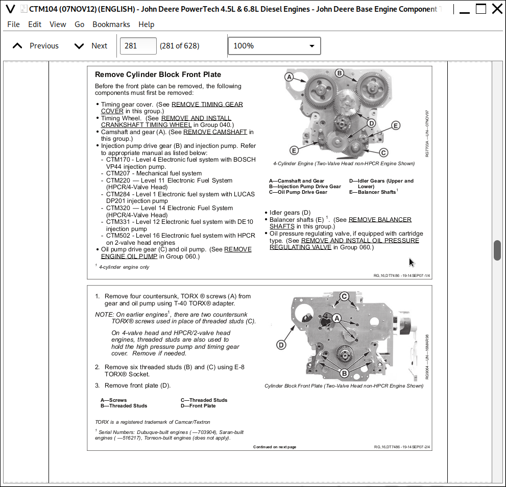
Remove Cylinder Block Front Plate....247
Measure Idler Gear Bushing and Shaft....250
Remove Idler Gear Bushings....251
Install Idler Gear Bushings....252
Remove Lower and Upper Idler Shafts....253
Clean and Inspect Front Plate....253
Transfer Fuel Injection Pump Timing Mark onto Replacement Front Plate ....254
Install Idler Shaft Spring Pins (If Equipped)....255
Install Upper Idler Shaft in Front Plate....255
Install Lower Idler Shaft in Front Plate....256
Install Cylinder Block Front Plate....256
Install and Time Balancer Shafts (4-Cylinder Engines)....258
Install Camshaft....262
Clean and Inspect Timing Gear Cover....265
Install Timing Gear Cover....266
Install Crankshaft Front Wear Sleeve and Oil Seal ....268
Remove and Install Magnetic Pick-Up Sensor ....270
Replace Mechanical Tachometer Adapter....271
Complete Final Assembly....272
Lubrication System....273
General Lubrication System Information....273
Remove, Inspect, and Install Oil Filter Base....273
Remove, Inspect, and Install Oil Cooler....277
Remove, Inspect, and Install Oil Bypass Valve....281
Remove and Install Oil Pressure Regulating Valve and Seat....281
Remove and Install Oil Fill Tube....284
Remove and Install Dipstick Tube with Oil Pan Installed....285
Remove and Install Dipstick Tube with Fitting....286
Remove, Inspect and Install Oil Pump Pick-Up Tube Assembly....287
Engine Oil Pump Assembly....287
Remove Engine Oil Pump....288
Inspect and Measure Clearances....289
Complete Oil Pump Disassembly....291
Assemble Engine Oil Pump....292
Install Engine Oil Pump....293
Install Oil Pan....295
Cooling System....297
Remove Water Manifold/Thermostat Cover and Thermostat ....297
Install Water Manifold/Thermostat Cover and Thermostat ....298
Remove and Install Water Manifold/Thermostat Cover and Thermostat (6010 Series Tractors with Single Thermostat) ....300
Remove and Install Water Manifold and Thermostats (Dual Thermostats) ....303
Test Thermostat(s)....304
Remove Water Pump....305
Water Pump Assembly....306
Disassemble Water Pump....307
Inspect, Clean, and Measure Water Pump Parts....308
Assemble Water Pump....309
Install Water Pump....310
Cooling System Deaeration....311
Remove and Install Automatic (Spring) Belt Tensioner....312
Checking Belt Tensioner Spring Tension and Belt Wear....312
Manual Belt Tensioner Adjustment ....314
Inspect and Install Fan Assembly....315