
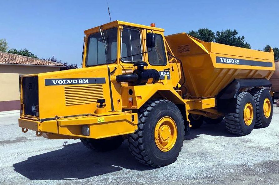
Volvo BM A25 4x4 6x4 Articulated Hauler Workshop Repair Service Manual PDF - MVOLCOA25.zip
A full-coverage service and repair manual, complete with electrical wiring schematics, for the A25 Volvo BM, the A25 4x4 Volvo BM, and the A25 6x4 Volvo BM — containing every workshop detail needed to service, troubleshoot, fix, and rebuild these machines the way trained technicians do.
The ART-A25 Volvo BM articulated hauler workshop service repair manual covers:
* Numbered table of contents easy to use so that you can find the information you need fast.
* Detailed sub-steps expand on repair procedure information
* Numbered instructions guide you through every repair procedure step by step.
* Troubleshooting and electrical service procedures are combined with detailed wiring diagrams for ease of use.
* Notes, cautions and warnings throughout each chapter pinpoint critical information.
* Bold figure number help you quickly match illustrations with instructions.
* Detailed illustrations, drawings and photos guide you through every procedure.
* Enlarged inset helps you identify and examine parts in detail.
Articulated Haulers A25 Volvo BM Service Repair Manual.pdf
PRODUCT DETAILS:
Pages: 801
File Format: PDF (Windows & Mac & Linux)
Language: English
Articulated Haulers A25 Volvo BM, A25 4x4 Volvo BM, A25 6x4 Volvo BM Service Repair Manual
Main Sections
0 - GENERAL
1 - STANDARD PARTS, SERVICE
2 - ENGINE WITH MOUNTING AND EQUIPMENT
3 - ELEC. SYSTEM; WARNING SYSTEM; INFORMATION SYSTEM; INSTRUMENTS
4 - POWER TRANSMISSION
5 - BRAKE
6 - STEERING
7 - FRAME; SPRINGS; DAMPING; AXLE SUSPENSION; WHEEL_TRACK UNIT
8 - MACHINERY HOUSE; CAB; EXTERIOR TRIM PARTS ANYWHERE
9 - HYDRAULIC SYSTEM; DIGGING_HANDLING_GRADING EQUIPM.; MISC EQUIPM
TABLE OF CONTENTS
000 - Foreword......2
000 - GENERAL......3
00 - DESCRIPTION; COMPLETE MACHINE......4
Description......5
03 - SPECIFICATIONS......6
Capacities......7
DIMENSIONS......8
Type Plates......11
Volvo standard tightening torques......12
Weights ......14
08 - TOOL......15
Drawings of E-tools which can be made in your own workshop......16
Instructions for checking control unit with ZF test instrument model PR-61 (1 PO1 137 304)......26
001 - STANDARD PARTS, SERVICE......40
17 - SERVICE......41
Electric welding......42
Towing......43
19 - GENERAL......44
A few simple rules for batteries......45
A few simple rules of safety......46
A few simple rules when inflating tyres......49
A few simple rules when servicing......50
Air conditioning......54
Charging batteries......55
Danger in connection with polymer materials......56
Measures to prevent fire......58
Refrigerant (R12)......61
Refrigerant (R134a)......62
Safety concerns everybody!......63
Service position......64
Starting with booster batteries......66
002 - ENGINE WITH MOUNTING AND EQUIPMENT......67
20 - GENERAL......68
Description......69
21 - ENGINE......70
Capacities......71
Component weights......72
Engine and transmissionremoving and fitting......73
Engine, removing and fitting......80
General-[2512]......83
General......84
Tightening torques ......85
Tightening torques-[2610]......86
Torque-tightening of cylinder head......87
Valves, adjusting......89
22 - LUBRICATING SYSTEM......91
General ......92
23 - FUEL SYSTEM......93
Adjusting counter-trottle cylinder for the throttle control......94
Adjusting load sensor on machines ser. no. 4329......95
Adjusting throttle control on machines with Ser. no. 4357......97
Capacities-[1952]......98
Fuel injection pump, changing......99
Fuel system, air bleeding......102
General-[1659]......104
General-[1844]......105
General-[2023]......106
Injection pump, checking and adjusting (alternative 1)......107
Injection pump, checking and adjusting (alternative 2)......109
Stalling speed, checking......111
25 - INLET & EXHAUST SYSTEM......112
General-[1553]......113
General-[1623]......114
26 - COOLING SYSTEM......115
Capacities ......116
Cooling fan motor, checking hydaulic system......117
Cooling fan, fault-tracing of hydraulic system......120
General-[1257]......122
General-[1455]......123
Hydraulic motor for fan, or hydraulic pump, checking for internal leakage......124
Hydraulic motor for fan, reconditioning......128
Hydraulic system, fan drive......137
Radiator, changing......139
Thermostat valve, reconditioning......141
Thermostat valve......143
003 - ELECTRICAL; WARNING; INFORMATION; INSTRUMENTS......145
30 - GENERAL......146
Description ......147
Special intructions for working on the electrical system......148
31 - BATTERY......149
General-[0844]......150
32 - ALTERNATOR; CHARGE REGULATOR......151
Alternatorregulator, fault tracing......152
General-[0705]......156
General-[0736]......157
33 - STARTING SYSTEM......158
General......159
Starting circuit, preheating......160
35 - LIGHTING......163
Bulbs......164
Headlights, adjusting......165
Lights, position......166
37 - CABLE; FUSE; RELAY......167
Codes in wiring diagrams......170
Compilation of circuits 3, 37, 71, 72, 76 and 87......180
Connector A. Engine hood, front right......183
Connector B. Left fender, battery box......184
Connector BM. Right cab wall, connection to control unit......185
Connector BN 1 .Left distribution box, connector socket......187
Connector BN 1. Left distribution box, connector plug......188
Connector BN2. Left distribution box, connector plug......189
Connector BN2. Left distribution box, connector socket......190
Connector CA. Right distribution box, circuit board......191
Connector CB. Right distribution box, circuit board......192
Connector CC. Right distribution box, circuit board......193
Connector CD. Right distribution box, circuit board......194
Connector CE. Right distribution box, circuit board......195
Connector CF. Right distribution box, circuit board......196
Connector CG. Right distribution box, circuit board......197
Connector CH. Right distribution box, circuit board......198
Connector CJ. Right distribution box, circuit board......199
Connector CK. Right distribution box, circuit board......200
Connector CL. Right distribution box, circuit board......201
Connector CM. Right distribution box, circuit board......202
Connector CN. Right distribution box, circuit board......203
Connector CO. Right distribution box, circuit board......204
Connector CP. Right distribution box, circuit board......205
Connector CS. Right distribution box, suspended......206
Connector CT. Right distribution box, suspended......207
Connector CU. Right distribution box, suspended......208
Connector D. Cab roof, wiper motor for windscreen......209
Connector E. Centre panel, suspended......210
Connector F. Left panel, suspended......211
Connector FS. Right distribution box, gear selector control......212
Connector GA. Left panel, suspended......213
Connector GB. Left panel, connector plug......214
Connector GB. Left panel, connector socket......215
Connector GE. Right side of transmission......216
Connector H. Centre panel, speedometer......217
Connector J. Right panel, suspended......218
Connector KA. Centre panel, left......219
Connector KB. Centre panel, right......220
Connector KC. Centre panel, centre......221
Connector L. Right panel, suspended......222
Connector LG. Left side, engine compartment, by oil cooler......223
Connector M. Right panel, suspended......224
Connector MV1. Left side, hydraulic transmission......225
Connector N. Right panel, suspended......226
Connector NA. Right panel, suspended......227
Connector O. Right panel......228
Connector P. Centre panel, suspended......229
Connector PA. Centre panel, suspended......230
Connector R. Right distribution box, suspended......231
Connector S. Right distribution box, suspended......232
Connector TA. Left panel......233
Connector TG. Left side, hydraulic transmission......234
Connector U. Left distribution box floor, suspended......235
Connector V. Left distribution box floor, suspended......236
Connector XA. Cab rear right corner......237
Connector XB. Cab rear right corner......238
Connector XC Cab rear right corner......239
Connector XD. Cab rear right corner......240
Connector Y. Behind frame joint......241
Connector Z. Rear frame cross member......242
Connectors XA, XB, XC and XD......243
Earth (chassis) connections......244
Electrical symbols......246
Explanations to wiring diagrams, lead and component markings......251
Fuses......255
Left distribution box......256
List of sub circuits for wiring diagrams......257
Not marked. Right distribution box, suspended......260
Position of connectors......261
Right distribution box......264
Wiring diagram 1 (9)......266
Wiring diagram 2 (9)......268
Wiring diagram 3 (9......270
Wiring diagram 4 (9)......273
Wiring diagram 5 (9)......276
Wiring diagram 6 (9)......279
Wiring diagram 7 (9)......282
Wiring diagram 8 (9)......285
Wiring diagram 9 (9)......288
38 - INSTRUMENT; SENSOR; WARNING & INFORMATION SYSTEM......291
Central Warning system (Figs)......292
Checking load sensor......297
Fault-tracing on circuit board, example 1......299
Fault-tracing on circuit board, example II......302
General-[2915]......305
General-[3223]......306
Induction sender, tipping limitation, testing......307
Instruments and controls......308
Magnetventiler......310
Tipping limitation (6x4, 6x6)......311
Warning system, brakes, (included in central warning system)......313
004 - POWER TRANSMISSION......318
40 - GENERAL......319
Description-[2717]......320
41 - CLUTCH; TORQUE CONVERTER......322
Tightening torques-[2619]......323
42 - TRANSMISSION; HYDRAULIC CONTROL......324
Capacities-[2450]......325
Checking gear selector......326
Checking solenoid valves, alternative to resistance measurements......327
Control system for automatic gear shifting, changing......328
Fault-tracing of hydraulic system for transmission......332
Fault-tracing outside control unit......333
Fault-tracing......336
General-[2203]......338
Hydraulic diagram, transmission (with retarder)......340
Hydraulic diagram, transmission (without retarder)......343
Inductive sensor for output shaft, changing......346
Inductive sensor for turbine speed, changing......349
Load sensor......353
Oil distributor, transmission......354
Pressure build-up......355
Safety functions......357
Sealing ring on output shaft, changing......359
TRANSMISSION PT 1050, description......362
Tightening torques-[2543]......364
Transmission PT 1050 removing......365
Transmission PT 1050, fitting......371
Transmission PT 1050......375
Transmission hydraulics......377
Transmission oil pressures, checking......379
Transmission, removing from engine......381
Wheights ......383
43 - GEARBOX......384
Capacities-[1456]......385
Descript......386
Dropbox FL-652 B......388
Dropbox, removing and fitting......391
Front output shaft on dropbox, changing seal......395
Gear-changing device, adjusting (on machine)......399
General-[1231]......400
Input shaft on dropbox, changing seal......401
Longitudinal differential lock, adjusting......404
Rear output shaft on dropbox, changing seal......407
Tightening torques-[1058]......410
Weights-[1032]......412
45 - PROPELLER SHAFT......413
Intermediate bearing in frame joint, changing bearing and seals......414
Propeller shaft, changing (between transmission and dropbox)......421
Tightening torques-[0956]......423
46 - FRONT AXLE; REAR AXLE......424
Capacities ......425
Dog clutch for six-wheel drive (6 x 6), checking and adjusting......426
Drivaxlar AH54......428
Front drive axle complete, removing......431
General-[0501]......436
General-[0646]......437
Tansverse differential lock, checking and adjusting (Applicable for all axles)......438
Tightening torques-[0620]......440
Trailing wheel axle, load unit......443
Weights-[0532]......444
48 - POWER TAKE OFF......445
Flywheel housing (rear engine transmission) and power take-off......446
General-[0333]......450
Power take-off on flywheel housing, reconditioning (Rear engine transmission)......451
005 - BRAKE......460
50 - GENERAL......461
Compressed air diagram, A 25......462
Description-[1247]......466
Function of brake system......467
General-[1146]......473
51 - WHEEL BRAKE......474
Brake pads, changing (one wheel)......475
Weights-[1119]......479
52 - HYDRAULIC BRAKE SYSTEM......480
Bleeding brake system......481
Capacities-[0938]......485
55 - PARKING BRAKE......486
Automatic brake adjuster......487
Description......489
General-[0533]......490
General-[0810]......491
Parking brake valve, hand control......492
Parking brake valve, reconditioning (removed)......497
Parking brake, changing brake disc......500
Parking brake, changing brake pads......503
Tightening torques-[0710]......507
Weights......508